
POWER TOOLS · PACK & PCB INTERFACES
Power-tool battery connectors.
From pack to PCB.
Choose the contact structure from the pack’s insertion path, final position and electrical load. Then compare the exact mating drawings.
Real Kangsheng parts. Open drawings. A clearer starting point for your next battery interface.
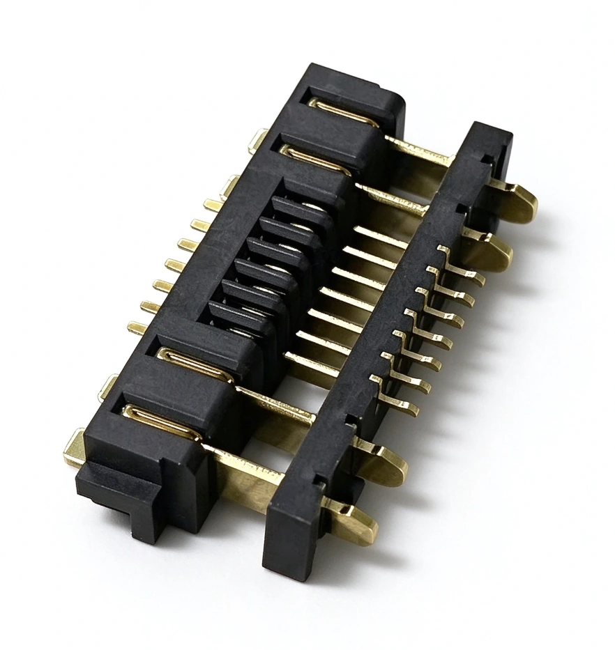 KS-HC-11M / KS-HC-11FMixed-contact structure
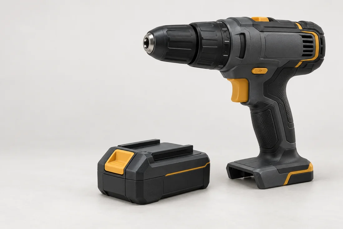
START WITH THE CIRCUIT
Choose a starting model for each circuit.
Start with the large-contact KS-HC-11M / KS-HC-11F format for a motor-power interface with separate signal positions. Choose the 2 A spring contacts below for sensing, auxiliary circuits or low-current packs within their 12 V drawing rating. Each row links to the standard drawing that supplies its values.
| Circuit / structure | Kangsheng starting model | Standard drawing values | Source PDF |
|---|---|---|---|
| Main power + separate signals | KS-HC-11M / KS-HC-11F | 2 + 7 + 2 layout; female large contacts: 25 A rated / 30 A momentary. | 11F female PDF ↗ |
| Lower-current blade interface · male | KS-2.5-M-VSMTPOST | 2.5 mm pitch; male drawing: 5 A / 30 VAC. | Male PDF ↗ |
| Lower-current blade interface · female | KS-BL-352 · 4 contacts | 2.5 mm pitch; female drawing: 7 A rated / 10 A momentary. | 4-contact female PDF ↗ |
| Sensing / auxiliary · side press | BC-75-3PD540 / 650 | 2 A / 12 V; standard housing heights 5.4 / 6.5 mm. | BC-75 series PDF ↗ |
| Sensing / auxiliary · top press | BC-82-3PD550 | 2 A / 12 V; 5.50 mm housing, 3 contacts. | 3PD550 PDF ↗ |
| Low-current pack / auxiliary | BC-30-3PD series | 2 A / 12 V; 3 mm pitch, 3 contacts, 8 / 9 / 10 mm housing variants. | BC-30 series PDF ↗ |
The blade male and female rows are individual drawing references. Compare their complete mating views, pin count and insertion depth before selecting a pair. For 11PIN, send the motor voltage, continuous load and peak duration with the mating drawing.
01 / FROM MOTION TO CONTACT
Start with the way the pack seats.
A removable tool battery needs an interface drawing that connects the pack’s motion to its final position. Identify the guide rails, keying, release mechanism and hard stop before choosing a spring or blade contact. The contact’s job is to make an electrical connection at that final position; the enclosure and retention features define how the pack arrives and stays there.
Follow the movement from first contact to the locked position. Mark where the pack enters the rails, where the terminals begin to engage and which surface stops further insertion. Include the release motion as well. Review the board support and housing together so insertion and removal loads have a defined mechanical path.
Show the pack’s insertion direction, the contact-loading direction and the PCB normal. They describe different things. A pack sliding horizontally can still meet a contact that loads vertically.
02 / CHOOSE THE STRUCTURE
Blade, side-press or top-press?
Blade contacts need a defined mating opening, overlap and insertion stop. Spring contacts need a defined loaded position and contact force. Select between them using the actual counterpart and available space. A shared pitch or a similar photograph does not supply those assembly dimensions.
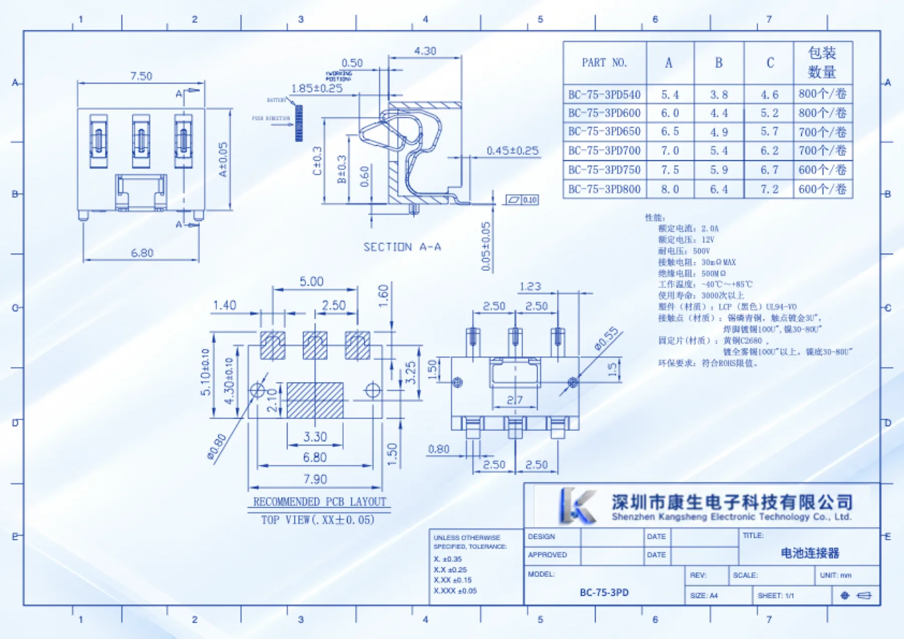
Side-press spring contact
BC-75-3PD540 and 650 have A heights of 5.4 and 6.5 mm. The side dimensions 1.85 and 0.50 mm give a nominal 1.35 mm displacement. Add the real pack, PCB and stop tolerances before calculating the assembled range.
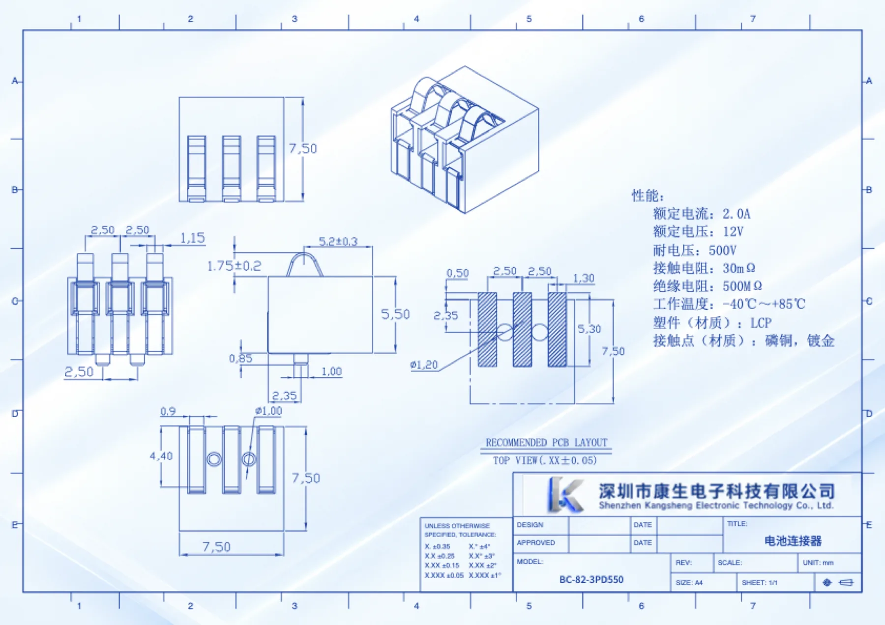
Top-press spring contact
The 3PD550 drawing gives a 5.50 mm housing and 1.75 ± 0.2 mm free projection. It does not label a working or maximum compression position. Send the assembly height to establish the loaded position instead of treating free projection as usable travel.
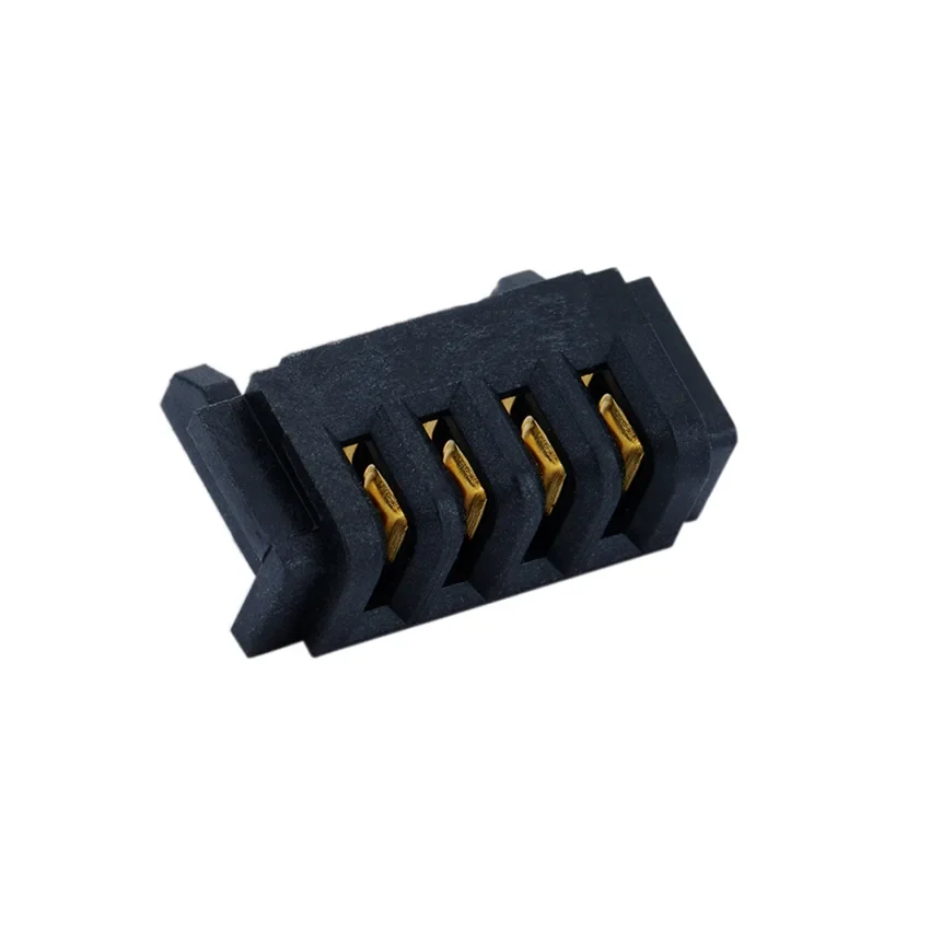
For a blade interface, compare both part drawings from the same viewing direction. Check blade width and thickness, cavity clearances, polarity, keying and the depth at the final stop. Read contact direction alongside the mating-orientation guide; the latter’s existing example uses a different 2 mm interface.
03 / SPECIFY THE DUTY
A current number needs a load brief.
Separate the motor-power path from sensing and detection circuits before comparing ratings. For the power path, record continuous load, peak amplitude, duration and repetition. Then add operating voltage, simultaneous loaded contacts, conductors, ambient temperature and allowed temperature rise. Keep the protection-trip threshold in the system brief so it can be checked alongside the operating load.
TI’s battery-pack design guide distinguishes design current, protection functions and measured test conditions.[1] Apply the same reading discipline to the complete mating pair and its PCB termination. A short pulse rating needs a duration and thermal conditions before it can be compared with the tool’s load cycle.
| Selection input | What to provide | What it resolves |
|---|---|---|
| Main power | Voltage, continuous current, peaks and duty cycle | Contact pair and conductor assessment |
| Temperature | Ambient, loaded contacts and allowed rise | The actual thermal test setup |
| Signals | Pin numbers, circuit functions and sequencing | Sense / identification / communication layout |
| Mechanics | Final stop, tolerances and retention | Contact position and force path |
Keep the motor-power and auxiliary circuits on separate lines in the specification. That makes a 2 A sensing contact and a large power contact easy to compare against their own duties, with the return path and all simultaneously loaded contacts shown.
04 / OPEN THE SOURCE FILE
Real parts. Original drawings.
Use these references to compare structures and prepare a focused enquiry. Keep the drawing’s part number, contact count and tail variant attached to every dimension. Where a file represents one variant, use that variant in the assembly model.
BC-75-3PD540 / 650
A = 5.4 / 6.5 mm housing variants; nominal side displacement 1.85 − 0.50 = 1.35 mm.
Standard drawing: 2 A / 12 V. Use the pack, board and stop dimensions to calculate the assembled contact position.
BC-82-3PD550
3 contacts, 2.5 mm pitch, 5.50 mm housing; Ø1.00 locating post and Ø1.20 PCB hole.
Standard drawing: 2 A / 12 V. Send the battery contact height so we can define the loaded position around your PCB.
BC-30-3PD series
3 contacts, 3 mm pitch, A = 8 / 9 / 10 mm; 800 is the available STEP variant.
Standard drawing: 2 A / 12 V. The nominal 2.0 mm displacement describes MAX.Compression; choose the working position from your assembly.
2.5 mm blade references
KS-2.5-M-VSMTPOST male: 5 A / 30 VAC. KS-BL-352 four-contact female drawing: 7 A rated / 10 A momentary.
Match width, thickness, keying, insertion depth and contact numbering. Keep each drawing’s rating attached to its own part.
KS-HC-11M / KS-HC-11F
2 + 7 + 2 contacts; 2.0 / 5.0 mm mixed pitch. Female large-contact values: 25 A rated / 30 A momentary.
Send the load profile and numbered pinout with the selected mating views. The female PDF and two DWG drawings are available below.
Compare the 2.5 mm male and four-contact female views side by side. Align the numbered contacts and use the assembly stop to establish the final mating depth.
05 / MIXED CONTACTS
Power and signal positions have different jobs.
The KS-HC-11M male and KS-HC-11F female use a 2 + 7 + 2 layout: two large contacts on each side and seven signal positions in the middle. The mixed 2.0 / 5.0 mm pitch describes that physical layout. Number the contacts from a specified viewing direction and put the positive, negative and signal nets on the same interface drawing.
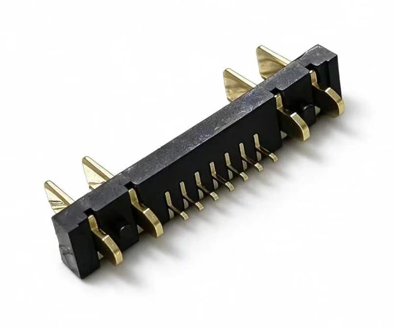
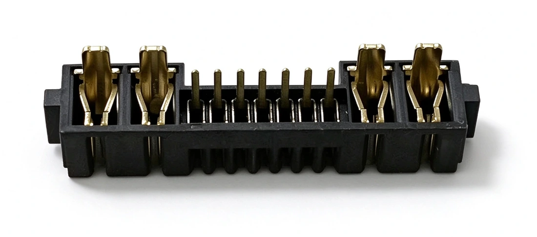
Temperature sensing, identification and communication each need a circuit assignment. List which signal is present, its voltage and current, and whether it must engage before or after the power contacts. Keep the connector’s physical pin numbers beside the tool and pack net names so the two halves can be checked in the correct orientation.
The 11PIN female drawing lists 25 A rated and 30 A momentary for each large contact. Those female values stay separate from the male, signal-contact and complete-pair ratings. Add the pulse duration and thermal conditions for the motor duty, with the supply and return paths identified. Open the female source drawing beside the system schematic.
06 / CLOSE THE ASSEMBLY LOOP
Define the PCB interface.
Distinguish electrical pads, locating holes and reference outlines. In the BC-82-3PD550 drawing, the Ø1.00 locating post and Ø1.20 PCB hole describe positioning; they do not replace the electrical pad definition. Carry the original view, datum and tolerance into the footprint review.
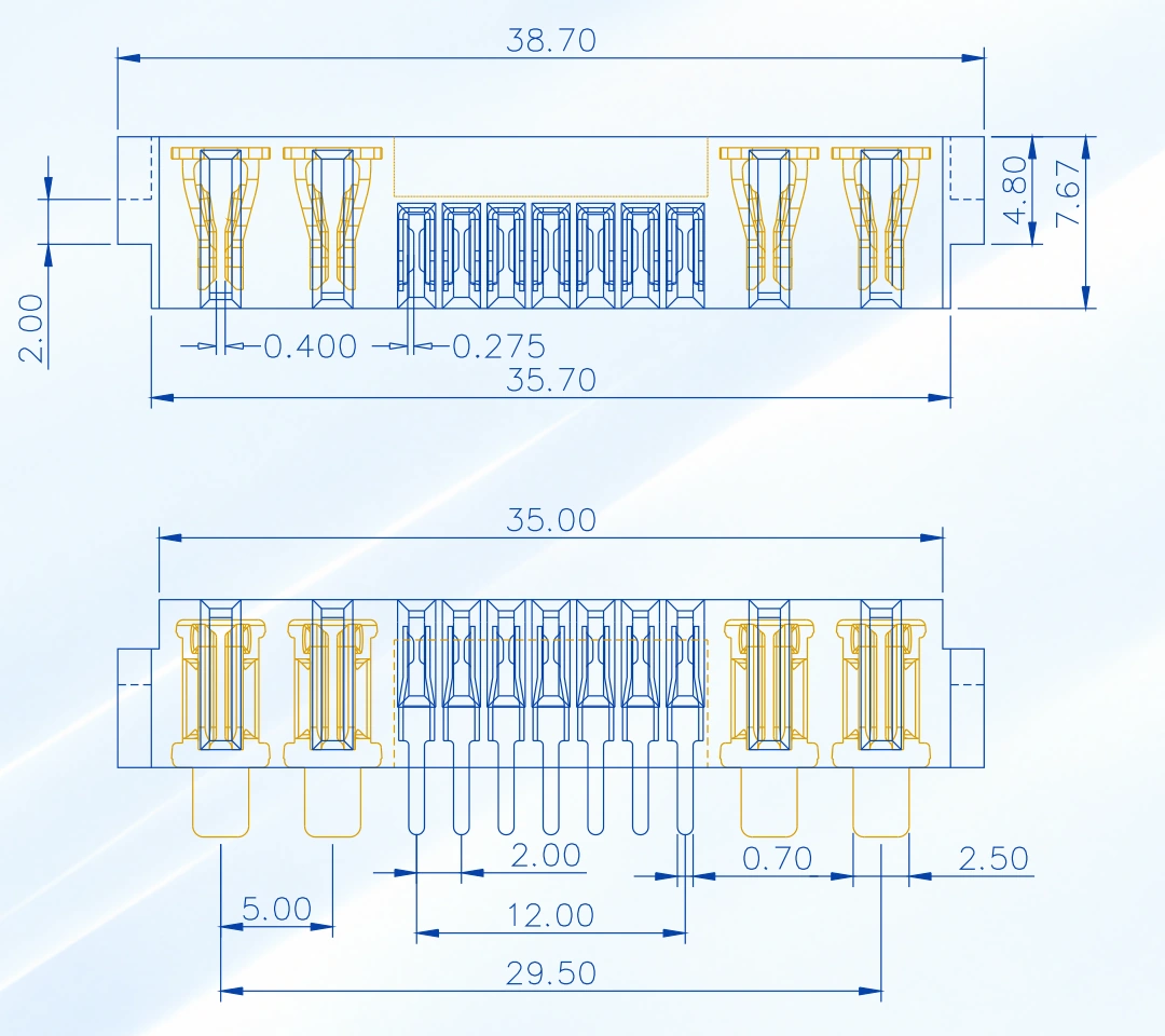
Use the selected connector’s PCB view to locate the terminal rows and mechanical features. Mark the component side, mating direction and board edge on your assembly drawing. Then add nearby components and enclosure walls to check access, clearance and support before ordering samples.
Specify board thickness, solder process, support and load transfer together. Review the connector’s process conditions against the actual board, solder materials and intended temperature/time profile. Use the PCB footprint guide to organize the views and the compression-stack guide for spring-contact assemblies. Standard free height and working height can be developed around your PCB space and battery contact plane.
BEFORE YOU REQUEST A SAMPLE
Five questions to settle first.
Can two 18 V battery packs use the same connector?
Only when their mechanical and electrical interfaces match. Compare the rails, insertion stop, keying, polarity and contact sequence on both drawings. Then supply the circuit pinout and sensing or communication requirements. Battery voltage is one input; the mating geometry determines whether the parts can connect.
Can the BC-75 or BC-82 carry an 18 V tool’s main motor current?
No. The cited standard drawings rate these parts at 2 A / 12 V. Select them for sensing, auxiliary circuits or low-current packs within those values. For a motor-power interface, start with the large-contact 11PIN format and send the voltage, continuous current, peaks and mating drawing for selection.
Does 30 A momentary mean the 11PIN pair carries 30 A continuously?
No. The KS-HC-11F female drawing specifies 25 A rated and 30 A momentary for each large contact. Those are female-contact values. Send the continuous load, pulse duration and repetition, conductor design and allowed temperature rise to select the complete male/female interface.
Are the seven smaller 11PIN contacts assigned to a standard pinout?
No. Your circuit defines the seven central signal positions. They can serve the temperature-sensing, identification or communication functions your design requires. Send a numbered net list, polarity and any first-mate or last-break sequence together with the mating views.
What do you need to review the PCB mounting and soldering?
We need the board layout and selected connector tail to review the mounting. Send board thickness, finished-hole or pad dimensions, assembly direction and mechanical support, together with the solder process and intended temperature/time profile. These inputs let us review the component, board and assembly process together.
YOUR NEXT INTERFACE
Send the drawing.
Start a precise conversation.
Share the mating views, available space, voltage, continuous and peak loads, signal assignments, mounting process and sample quantity. We can discuss the real catalogue files and the dimensions your assembly needs. Housing height can be developed around the available PCB space.
Technical reading & source drawings
The design guide below explains how system loads and test conditions are recorded. Kangsheng part values come from the individual linked drawings above.
- Texas Instruments · TIDA-00449 design guide ↗Sections 2, 4.1.2–4.1.3 and 6.2.1.1: design current, protection and test conditions.