
ASSEMBLY & SELECTION GUIDE
Spring Battery Connector Compression: A BC-75 Example
Use the BC-75 drawing to calculate 1.35 mm nominal compression, then check the complete assembly tolerance stack and seated contact position.
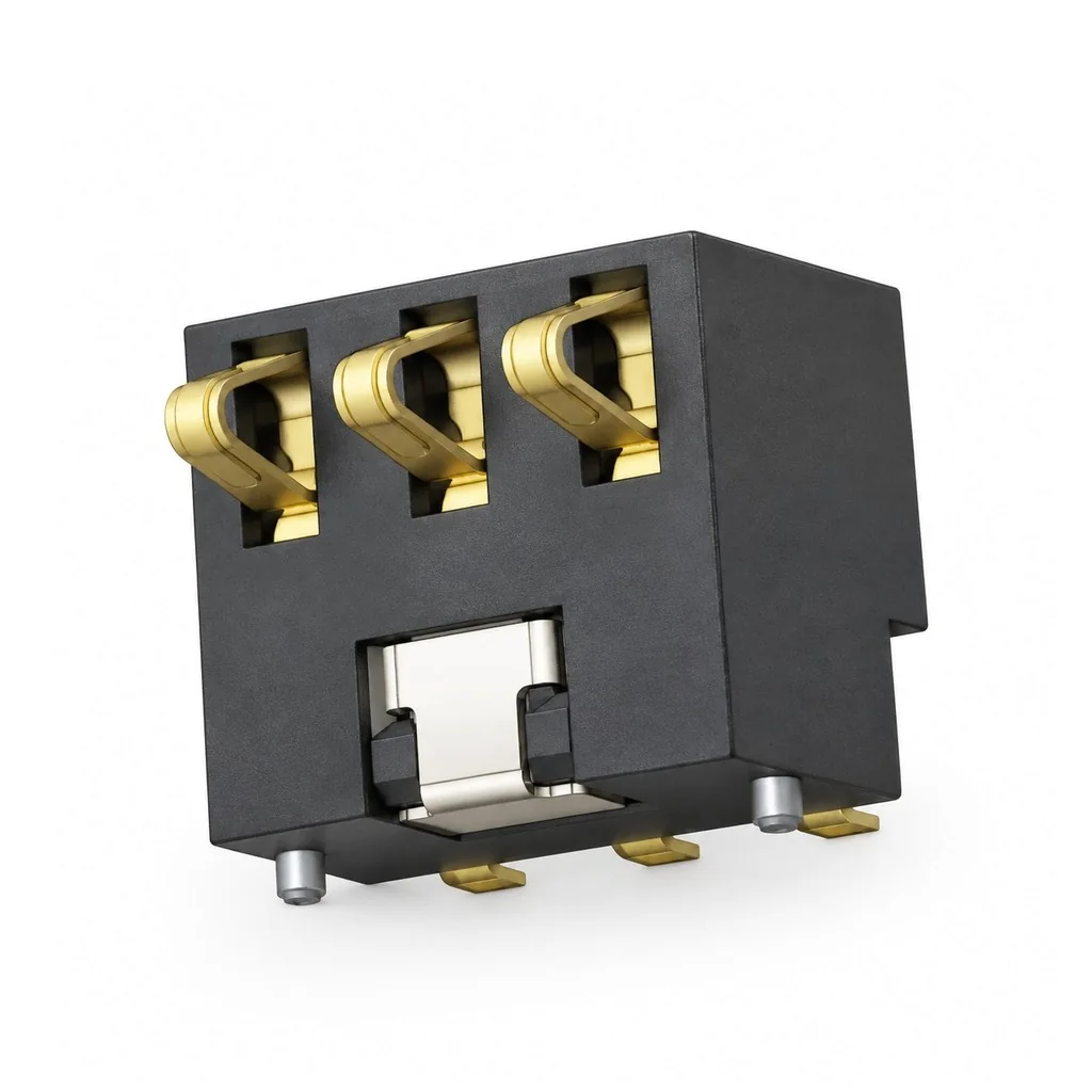
Key takeaways
- BC-75 nominal compression is 1.35 mm from the standard drawing; the full assembly stack determines the variation.
- Measure free position F and seated offset A from one housing face, along the actual compression axis.
- The worked example below separates drawing dimensions from three explicitly assumed assembly dimensions.
- Free height and working height can be customized around your PCB and battery compartment.
The standard BC-75-3PD drawing gives a nominal spring-contact compression of 1.35 mm: a 1.85 mm free projection minus a 0.50 mm working-position offset, measured from the same housing face along the push direction. To check an assembly, calculate its smallest and largest seated offsets as well.
For a handheld battery bay or a physical scanner cradle, compare the contact axis and installation envelope in the handheld, scanner and POS interface guide before applying the tolerance stack.
Read the free and working positions from one datum
A formed spring contact bends as the mating surface closes against it. Contact compression is the change in position along that movement. The housing envelope helps you fit the connector into the product; the contact positions tell you how far the spring moves.
For the side-press BC-75, start at the front face of the housing. The drawing shows a free projection of 1.85 ± 0.25 mm and labels the working position 0.50 mm from that face. Subtracting their nominal values gives 1.35 mm.
The top-press BC-35 uses the top face of its housing for the corresponding callouts: 1.85 ± 0.20 mm free projection and 0.40 mm working-position offset, giving 1.45 mm nominal displacement. Its overall 7.4 mm dimension has different endpoints. Use the local projection callout rather than subtracting unrelated envelope dimensions.
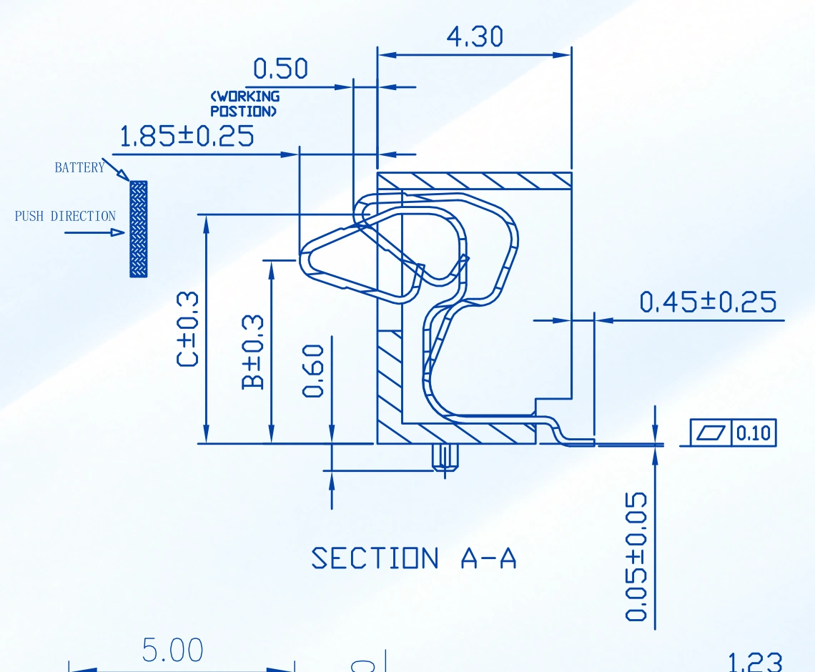
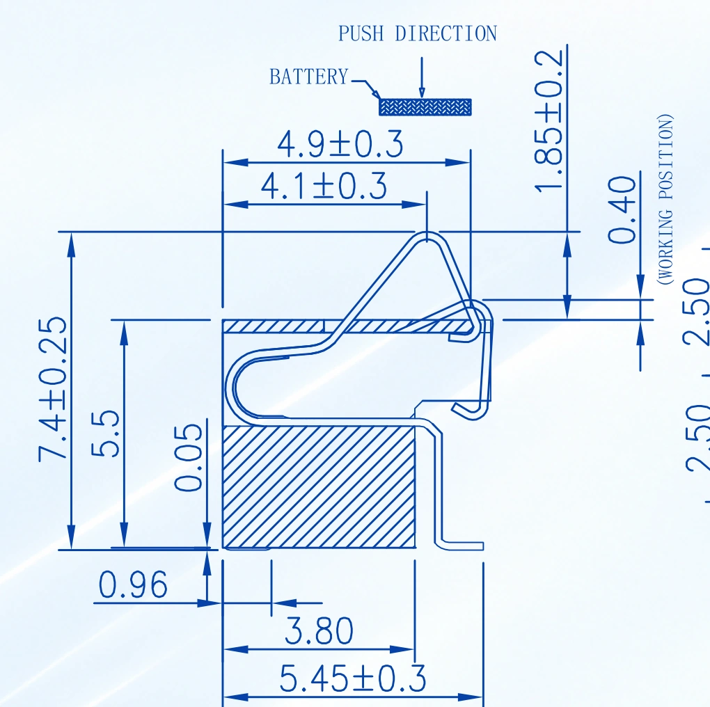
Open the original BC-75 series PDF or BC-35-3P550 PDF to inspect the complete extension lines and title-block tolerances. These are standard-part drawing values. Housing height, working position and a maximum travel limit answer different design questions.
Recognize the assembly signs
A battery that connects on the bench can still move to a different contact position when its latch, cover or PCB supports reach their tolerance extremes. Observe the seated condition before choosing a taller contact.
| Assembly observation | Inspect first | Useful comparison |
|---|---|---|
| Connection changes when the pack moves | Latch play and contact-plane tilt | Largest seated offset at each contact |
| One contact remains lower after removal | Unloaded contact and its support | An unused sample of the same variant |
| Marks concentrate on one edge | Guidance and contact landing area | Approach path against final seating |
| Housing closes before every contact engages | Stop position and unequal surfaces | Smallest and largest contact engagement |
| Local warmth appears under load | Current path and connection voltage drop | Electrical results at recorded operating conditions |
Keep the contact identity and assembly condition beside each observation. A continuity check records one electrical state; the geometric review still needs both tolerance extremes.
Find the feature that sets the closed position
The spring should follow the seated mating surface. A latch, enclosure shoulder or other mechanical stop should carry the final seating load. If tightening a cover keeps moving the contact plane, cover position belongs in the stack.
Trace the chain from the board support through the connector mounting position to the battery stop and contact face. Include board thickness only when it locates an endpoint in that chain. Adding it again because it appears elsewhere in the CAD model double-counts the same movement.
Check rotation separately. An angled battery plane can compress one end of a connector more than the other even when its centre coordinate is correct. Calculate the local seated offset at the first and last contacts.
Three device checks that change the stack
Application illustration. Each card combines an original Kangsheng connector photograph with an unbranded device illustration. Use the seating feature in each device to decide which dimensions enter the calculation.
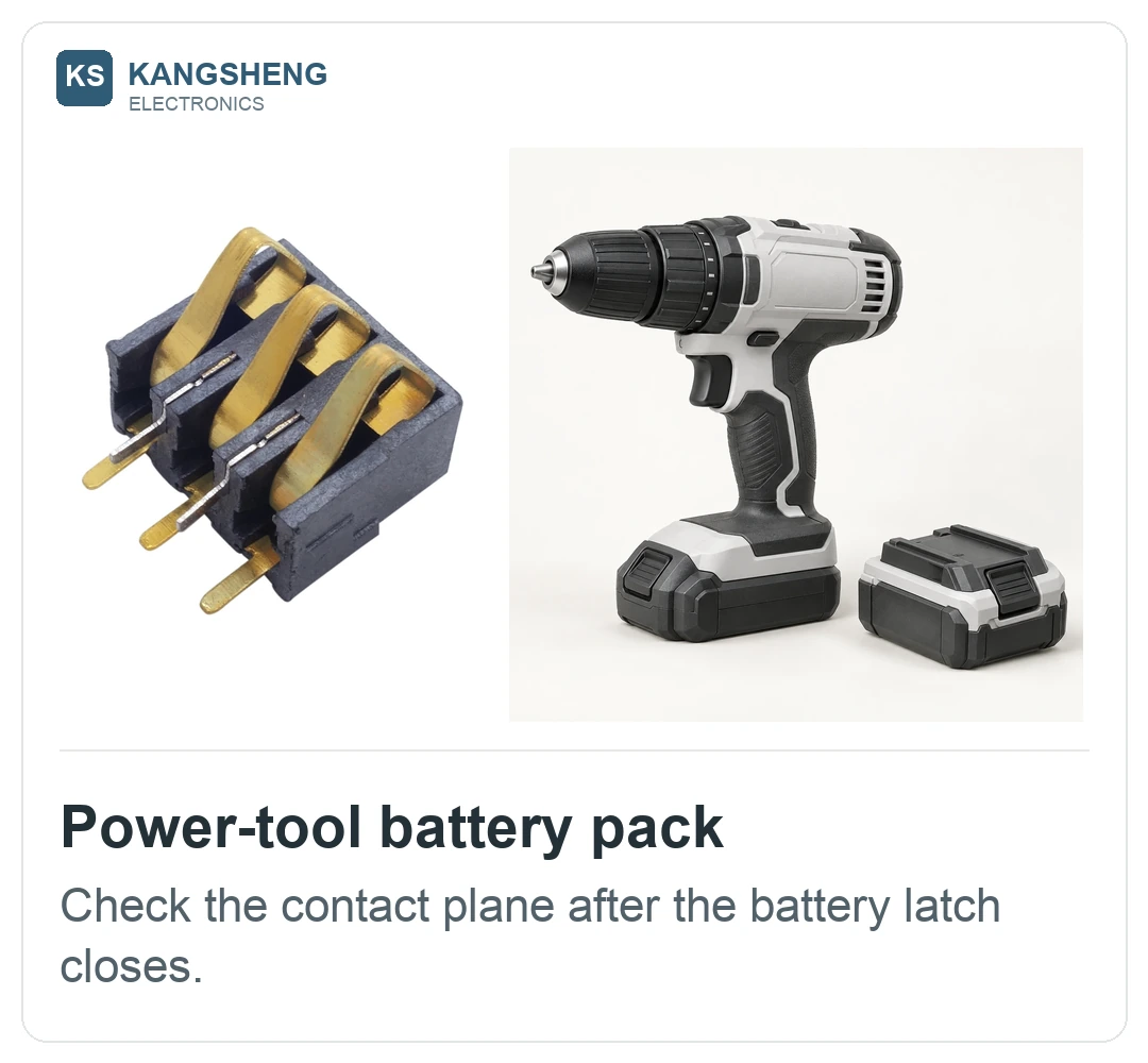
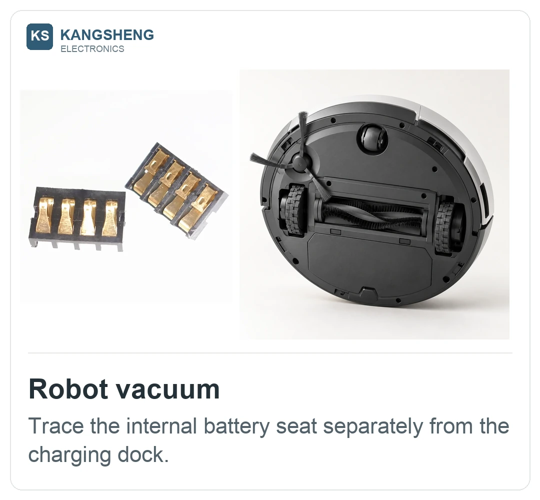
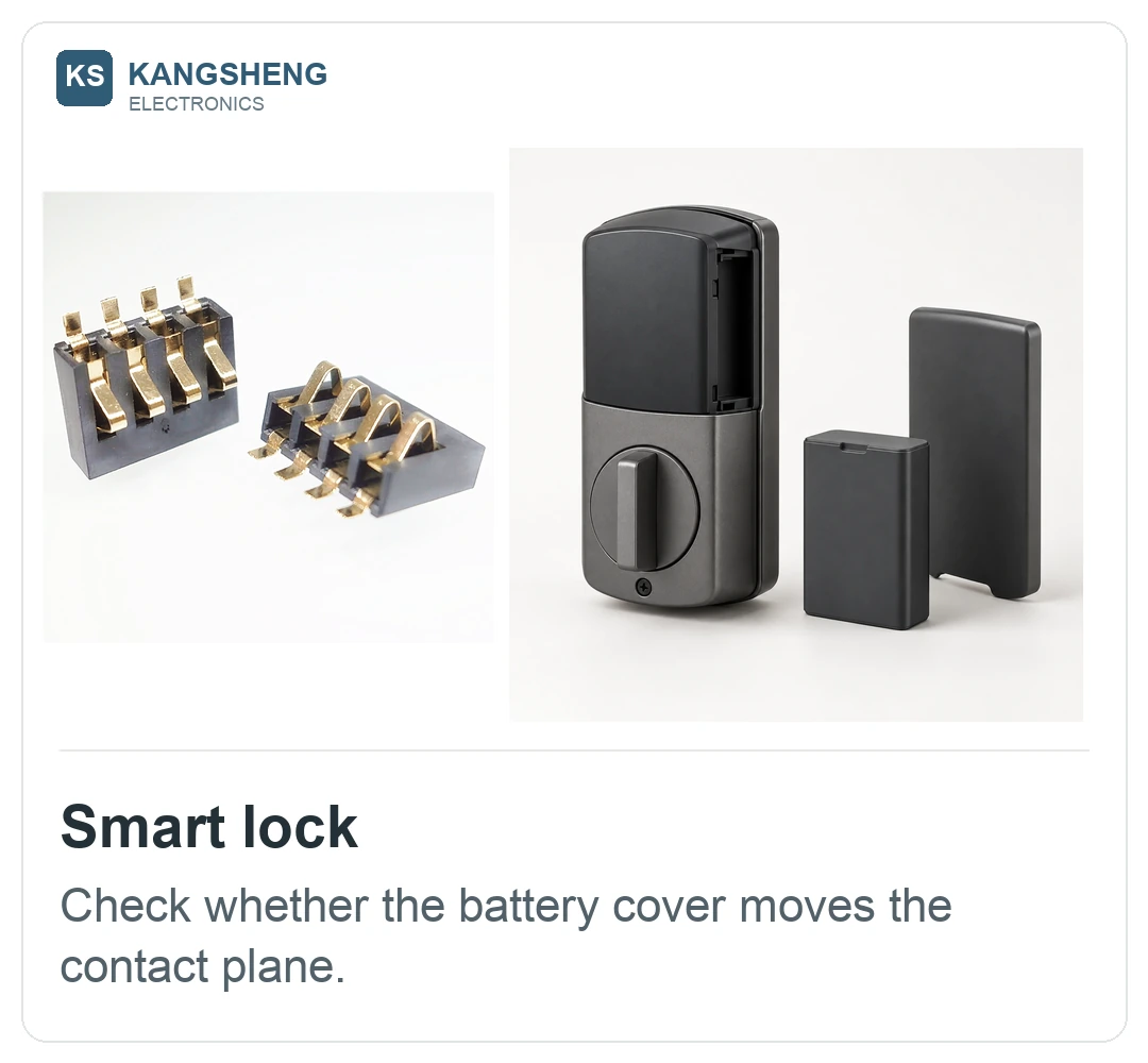
A tool pack's guide rails and latch locate the final seat. For a robot vacuum, the internal battery interface and external charging interface have different datums. In a lock, the cover may retain a cartridge while another shoulder establishes its contact position. Record the relevant interface before measuring clearances.
Calculate a complete BC-75 tolerance example
Use millimetres and one coordinate axis pointing from the connector toward the battery stop. Let C locate the housing front face and S locate the seated battery stop from a shared assembly datum. Let P be the positive distance from that stop back toward the connector to the battery contact face. The contact face coordinate is therefore S − P.
The following is an illustrative design stack. The three assembly dimensions are assumptions for this calculation; the free projection comes from the BC-75 drawing.
| Input | Value | Source |
|---|---|---|
| Free projection F from the housing face | 1.85 ± 0.25 mm | BC-75 standard drawing, contact section |
| Housing-face coordinate C | 10.00 ± 0.05 mm | Design assumption |
| Seated battery-stop coordinate S | 11.00 ± 0.05 mm | Design assumption |
| Stop-to-contact-face distance P | 0.50 ± 0.05 mm | Design assumption |
The seated offset from the connector housing face is A = S − P − C.
- Nominal: A = 11.00 − 0.50 − 10.00 = 0.50 mm.
- Minimum: Amin = 10.95 − 0.55 − 10.05 = 0.35 mm.
- Maximum: Amax = 11.05 − 0.45 − 9.95 = 0.65 mm.
The drawing gives Fmin = 1.60 mm and Fmax = 2.10 mm. Compression is δ = F − A, so combine the least free projection with the largest gap for minimum compression, and reverse them for the maximum.
| Result | Calculation | Compression |
|---|---|---|
| Nominal | 1.85 − 0.50 | 1.35 mm |
| Minimum | 1.60 − 0.65 | 0.95 mm |
| Maximum | 2.10 − 0.35 | 1.75 mm |
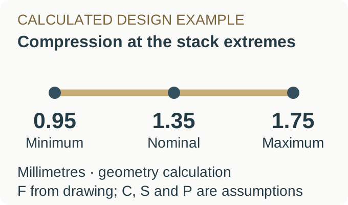
These limits combine independent dimensional extremes. Tilt, seating deformation and wear need their own inputs when they affect the contact plane. Replace C, S and P with dimensions from your assembly drawing before using the worksheet.
The BC-75 title block lists X.XX ± 0.15 mm for dimensions without individual tolerances. In this example, A's ±0.15 mm already comes from its three assembly contributors. Adding another ±0.15 mm from the drawing's nominal 0.50 callout would mix two descriptions of the seated position.
At 1.75 mm maximum compression, the contact face remains 0.35 mm ahead of the housing front face: the example still has a positive housing gap. At the other extreme, 1.60 − 0.65 = 0.95 mm, so the spring still reaches the contact face geometrically. If A becomes negative, the contact face passes the housing datum; move the stop or revise the mounting position to restore clearance.
The 0.95–1.75 mm interval is the calculated geometry of these assembly assumptions. Use it to set the example's stop and clearance; the BC-75 drawing's 0.50 mm working-position callout remains the standard-part reference.
Prevent excess closure before cutting tooling
- Identify the exact variant, mating surface and compression direction.
- Mark the housing datum and the final seated battery contact plane.
- Calculate both extreme offsets, including the locating features that actually move those planes.
- Set a mechanical stop that carries the seating load.
- Check the guided approach and contact-plane angle.
- Verify the resulting positions and electrical behaviour with representative assemblies.
Compare the fully seated assembly with the partly inserted condition. A satisfactory final position can still have an approach path that catches an edge or loads one contact first. Guidance and compression solve different parts of that problem.
Correct an existing assembly in the right order
If the contact remains short after unloading, compare it with an unused reference and inspect the housing support, mating surface and solder joints. Record which feature changed before replacing the connector.
Then review the dimension that set the closed position. Moving a stop, correcting a board support or changing the specified contact height addresses different causes. Choose the correction from the measured stack, then repeat the relevant mechanical and electrical checks. Replacing a deformed spring while keeping the same excessive closure repeats the original loading condition.
Choose a housing variant without treating height as stroke
The BC-75 series drawing includes these two installation envelopes:
| Series variant | Drawing A | Drawing B | Drawing C |
|---|---|---|---|
| BC-75-3PD540 | 5.4 mm | 3.8 mm | 4.6 mm |
| BC-75-3PD650 | 6.5 mm | 4.9 mm | 5.7 mm |
The 1.1 mm difference in A changes the installation geometry. The contact-section calculation remains the same 1.85 − 0.50 = 1.35 mm nominal displacement. Compare the BC-75-3PD540 and BC-75-3PD650 model pages with the A, B and C arrows in the original PDF.
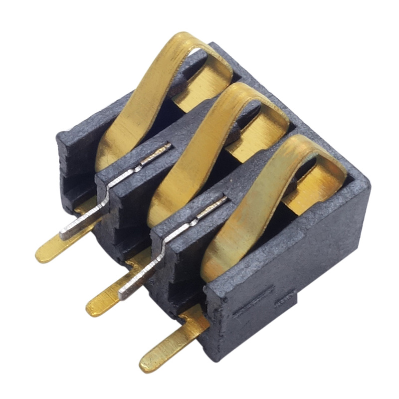
These original 2.5PH, three-position catalogue photographs show four housing and terminal arrangements:
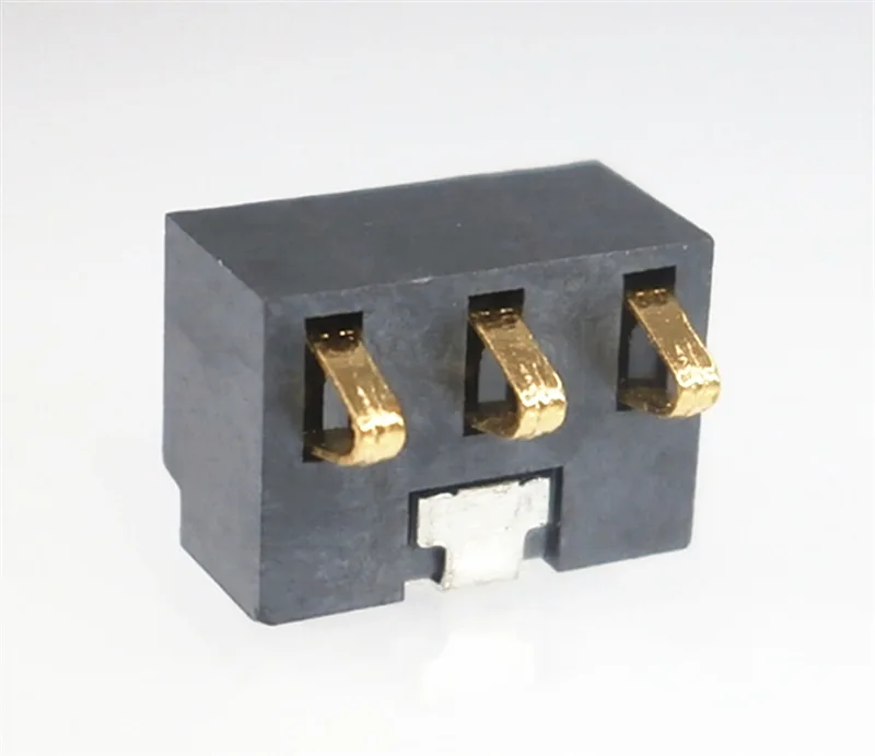
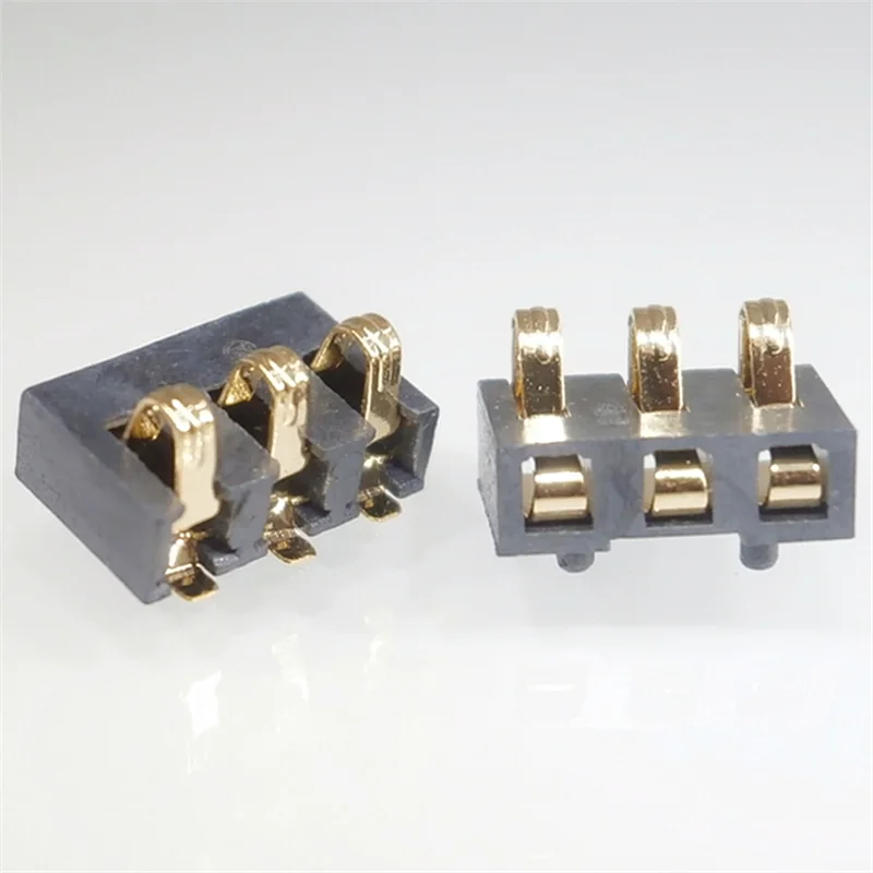
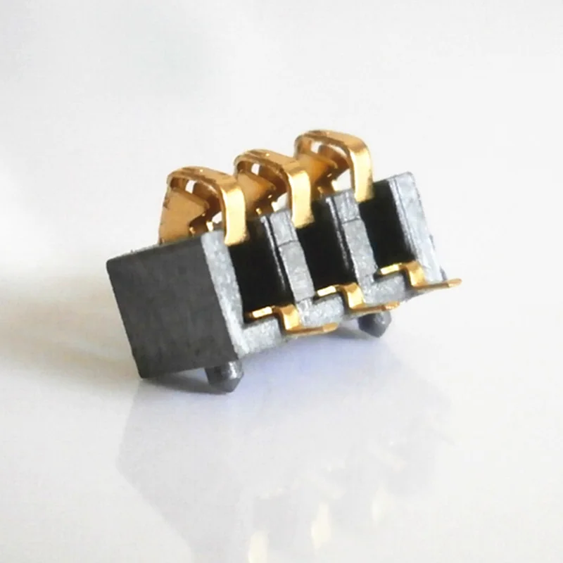
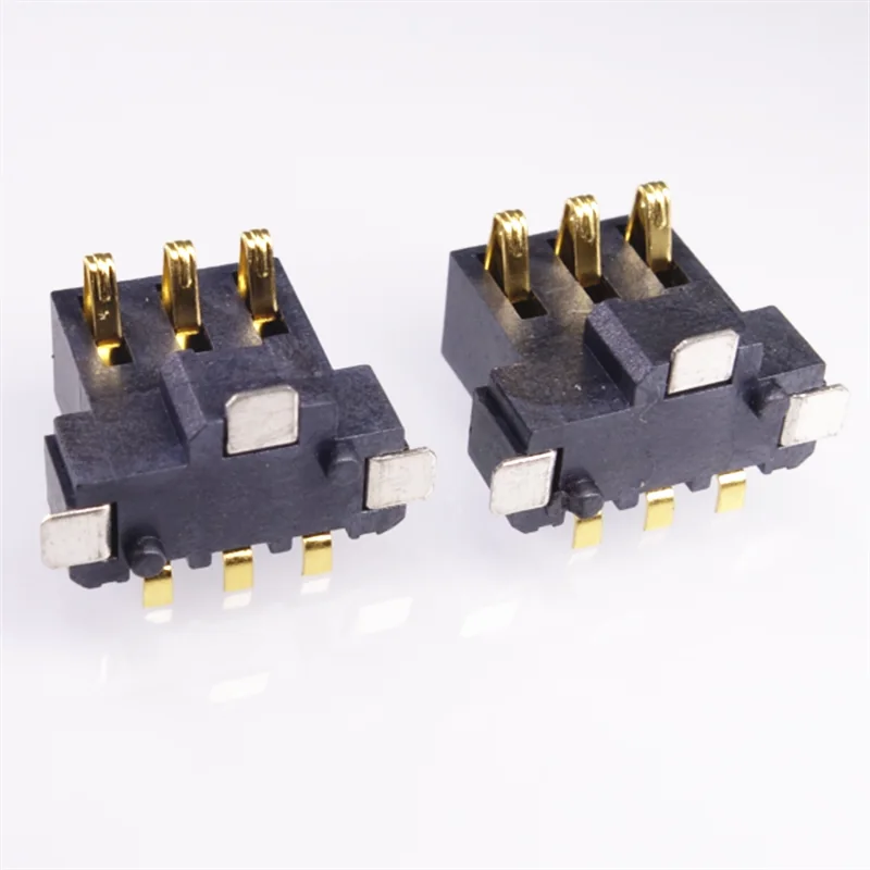
Compare the supports, terminal exits and contact openings. The H suffix identifies a catalogue variant; obtain its free and seated contact positions from its own drawing before calculating travel.
What Kangsheng can prepare from your assembly drawing
Kangsheng Electronics (Shenzhen Kangsheng Electronic Technology Co., Ltd.) can review the contact direction, pitch, installation envelope and required compression against your assembly. Free height and working height can be customized to your PCB space and battery compartment. Send the seated contact plane and its tolerance with the PCB reference, rather than a housing-height number alone.
For an existing part, include its complete model, the mating-face view and photographs of the terminals and supports. For a new layout, include your stop geometry, minimum and maximum offsets, current requirement and operating conditions. Those inputs give the height review a defined assembly to work with.
Read the contact-direction guide before changing from top press to side press, or open the custom connector page to prepare a drawing request.
CATALOGUE REFERENCES
Related products
Frequently asked questions
How much does a standard BC-75 contact compress?
Is 1.10–1.60 mm the complete BC-75 assembly tolerance range?
Can the BC-35 calculation use its 7.4 mm overall height?
Can standard free height and working height be changed?
Does 1.75 mm example compression close the housing gap?
YOUR NEXT DESIGN CHECK
Need a different working height?
Send your PCB reference, seated battery contact plane and tolerance stack. We can customize free height and working height around your assembly.
Request a height review Explore custom connectors →