
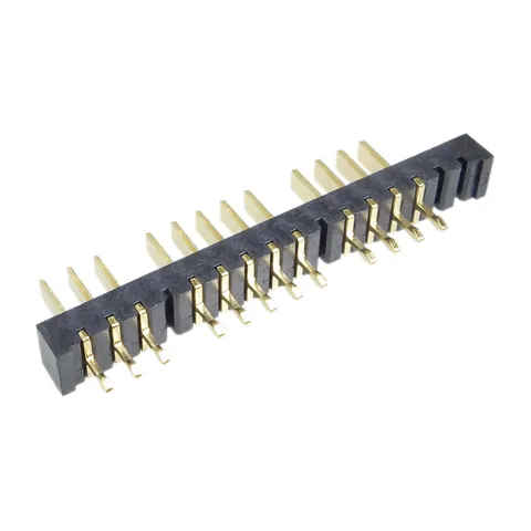
Male Blade-Type Battery Connector, Selectively Loaded
KS-BL-057
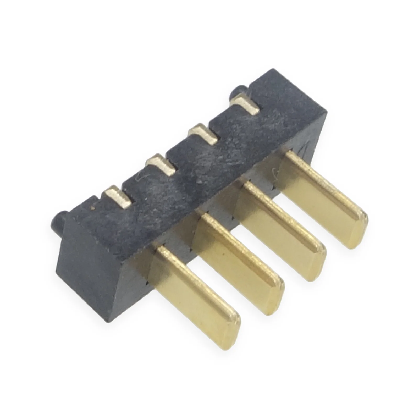
Kangsheng makes 102 blade battery connector models, including 2.0, 2.5 and 5.0 mm pitch options, with 2–20 pins; 38 have downloadable drawings.
For handheld, scanner and POS battery interfaces, compare spring and blade drawings by contact direction, mounting space and actual duty, with a separate record for each side.
KANGSHENG CATALOGUE REFERENCES
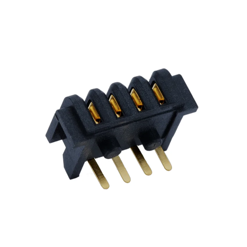
| Catalogue model / series | Drawing contents | Documents & details |
|---|---|---|
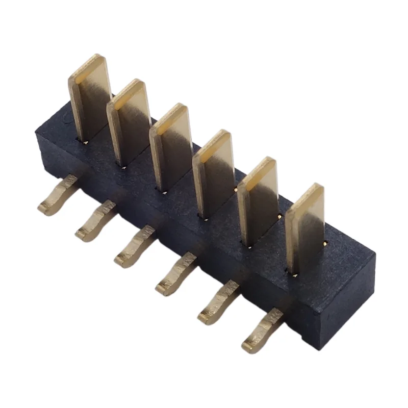
| KS-2.5-M-VSMTPOST | 3–16-position dimension rows | Model detailsSeries drawing PDF |
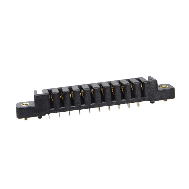
| KS-BL-352 | 4-position drawing | Model details4P drawing PDF |
HOW TO CHOOSE
Selecting a removable pack interface? Start with the power-tool battery connector interface guide and compare the mating drawings, insertion depth and load conditions.
PRODUCTS
KS-BL-057
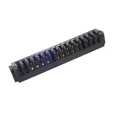
KS-BL-129
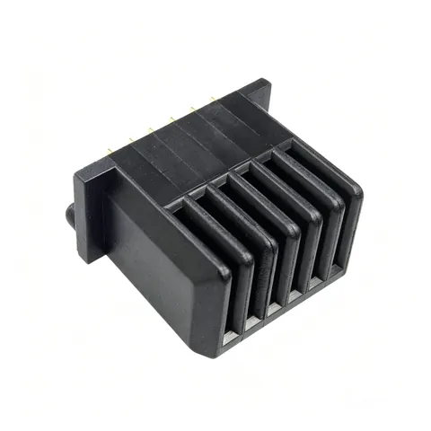
KS-BL-138
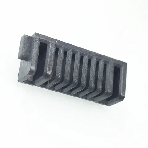
KS-BL-144
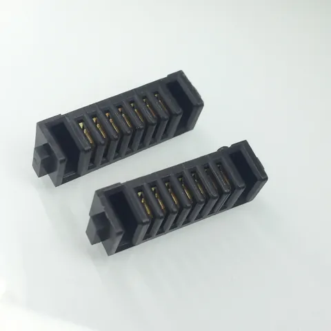
KS-BL-145
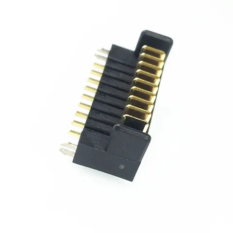
KS-BL-146
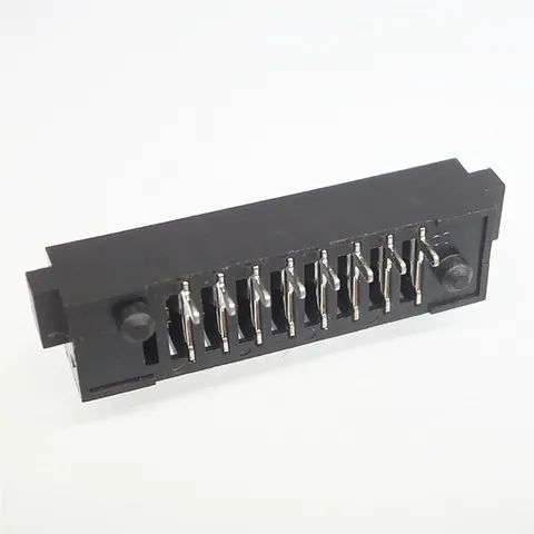
KS-BL-149
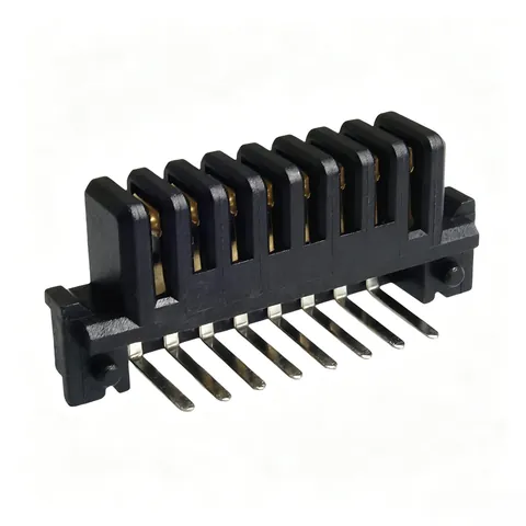
KS-BL-158
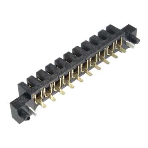
KS-BL-159
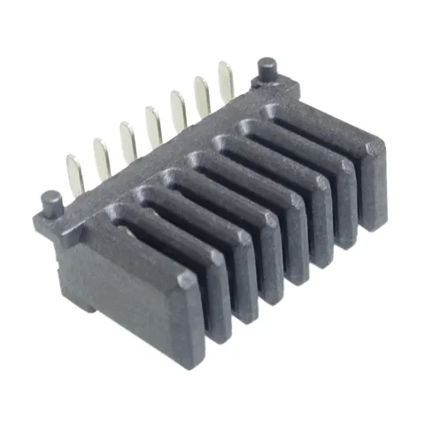
KS-BL-160
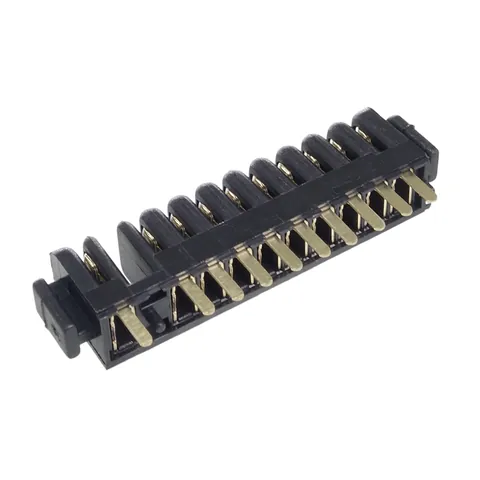
KS-BL-180
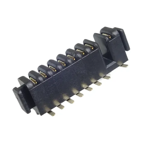
KS-BL-181
PART NUMBER DIRECTORY
APPLICATIONS
FAQ
The current published list contains 102 models. Filter by pitch, pin count and structure, then check the required assembly dimensions.
The recorded pitches are 1.5, 2, 2.5, 2.7, 5 mm. Filter by these individual specifications. Another 65 models feature custom or non-standard pitches; share your PCB interface drawing for custom matching.
The recorded pin counts in this list are 2, 3, 4, 5, 6, 7, 8, 9, 10, 11, 12, 14, 16, 20. Choose using the battery and device pinout definitions; matching pin counts do not establish matching functions or pin assignments. Another 32 models support modular or custom pin counts; contact us for application-specific pinouts.
The recorded forms in this list include Mated set, Female, Male. Obtain the specified mating part numbers and both drawings, then check pin count, keying and mating orientation. Form labels alone do not establish compatibility.
The current list includes 38 models with 2D drawings. Check the actual pin-count variant and drawing revision on the product page rather than measuring a photo.
Compare contact positions, insertion direction, polarity, keying and retention as well. Provide both complete part numbers and drawings, and compare interface dimensions and pin assignments.
Check insertion direction, contact locations and pin assignments first, followed by board holes, retention geometry and enclosure space. Identify power and signal contacts separately on the interface drawing.
Provide the complete part number, drawings of both sides of the interface, assembly space and sample quantity. List voltage, continuous and peak current, ambient temperature and cycle requirements separately for electrical evaluation.
Send the part number, quantity or a drawing and we will get back to you.