
HANDHELD DEVICES · BATTERY & CHARGING INTERFACES
Handheld, Barcode Scanner & POS Battery Connectors
Start at the interface.
For handheld terminals, barcode scanners and POS devices, start with the battery interface. For a removable single-cell 3.7 V battery bay, compare BC75 side-press contacts with 5.4 / 6.5 mm housings or the BC82 top-press design with a 3.0 mm housing. For main power above 2 A, start with blade structures. For a scanner cradle, define the seating guides and contact position; for a fixed POS, start at the adapter input.
Original Kangsheng photographs and drawings, tied to each model and variant.
03 / DRAWING-BACKED SELECTION
Six drawing-backed starting points.
The BC75, BC82 and four-contact BC28 drawings state 2 A / 12 V. Start with contact direction, housing height and installation space. The blade rows show each part’s mounting structure and drawing ratings.
| Interface task | Model & variant | Drawing values & mounting check | Source files |
|---|---|---|---|
| Battery bay with side-press contacts | KS-BC-75-3PD5403 contacts · 2.50 mm pitch · 5.4 mm housing | 2.0 A / 12 V0.50 mm working position from the housing front; add the assembly stack. | KS-BC-75-3PD540 PDF ↗KS-BC-75-3PD540 STEP ↗ |
| Taller side-press structure | KS-BC-75-3PD6503 contacts · 2.50 mm pitch · 6.5 mm housing | 2.0 A / 12 V6.5 mm housing; use the battery contact plane and assembly stack to set the working position. | KS-BC-75-3PD650 PDF ↗KS-BC-75-3PD650 STEP ↗ |
| Four-contact top-press interface | KS-BC-82-4PD3004 contacts · 2.50 mm pitch · 3.00 mm housing | 2.0 A / 12 VFree projection 1.75 ± 0.2 mm; define the working position in the assembly. | KS-BC-82-4PD300 PDF ↗KS-BC-82-4PD300 STEP ↗ |
| Compact 2 mm four-contact bay | KS-BC-28-4P340-C09Four-contact C09 series variant · 2.00 mm pitch · 3.40 mm housing | 2.0 A / 12 VUse the four-contact A/B/C row: 8.0/6.0/4.0 mm, and the 4P STEP. | KS-BC-28-4P340-C09 PDF ↗KS-BC-28-4P340-C09 STEP ↗ |
| Four-position male: vertical mating, SMT with posts | KS-2.5-M-VSMTPOSTSelected 4-position row · 2.50 mm pitch · 0.60 mm blade thickness | 5 A / 30 V ACFour-position vertical male with SMT tails and locating posts; check PCB pads and mating direction. | KS-2.5-M-VSMTPOST PDF ↗ |
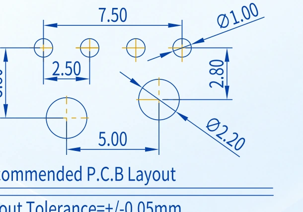
| Four-contact female: right-angle through-hole tails, square posts | KS-BL-352 · 4PB04F-4P-L2 square-post drawing · 2.50 mm pitch | 7 A; 10 A momentaryRight-angle through-hole tails and square posts; the 500 V entry is dielectric withstand. | KS-BL-352 · 4P PDF ↗ |
When selecting the mating parts, compare blade width and thickness, cavity entry, keying, numbering and engagement depth.
01 / LOCATE THE CONNECTION
Three device types. Find each interface.
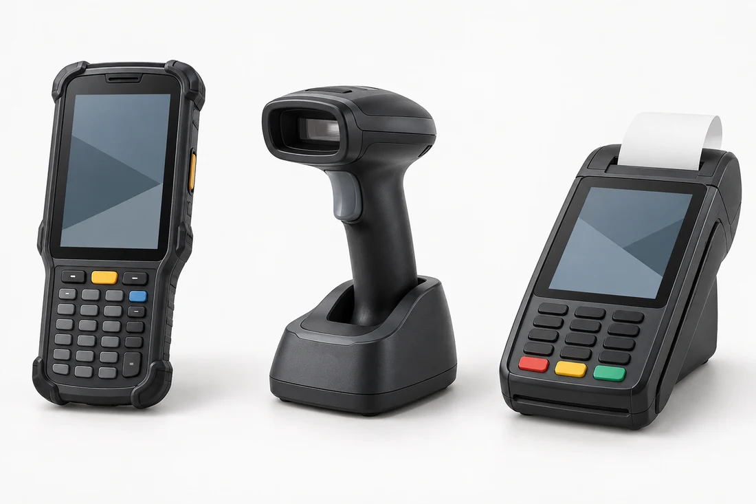
One device can have both an internal battery connection and an external charging connection. These scene cards place generic equipment beside real contact structures to frame the mounting discussion. Your assembly drawing defines the actual location.
Handheld terminal
Separate battery bay from device dock
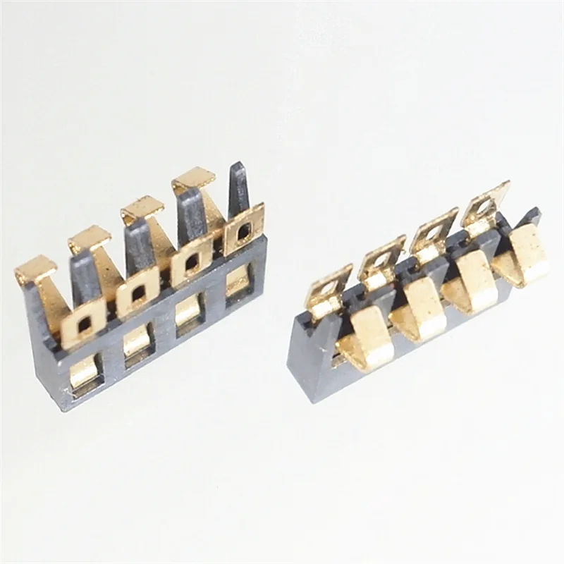
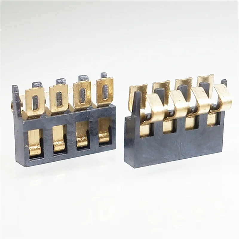 KS-BC-28-4P340-C09
Generic device illustration + real Kangsheng contact structure
A removable pack-to-board connection and a device-to-cradle connection are two different interfaces. Circle the one being designed, then compare its contact plane, final position and current path.
Barcode scanner
Separate wired host power from cordless-scanner charging
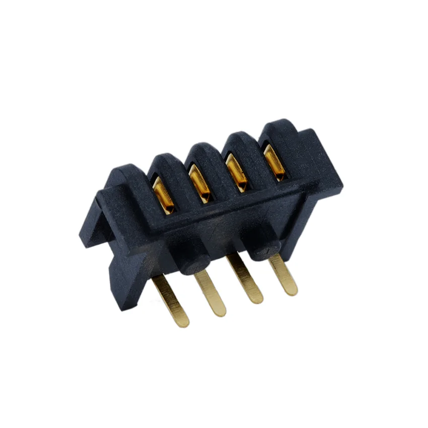 KS-BL-352 · 4P
Generic device illustration + real Kangsheng contact structure
Start at the cable entry for a wired scanner. For cordless versions, identify the battery arrangement and charging method. A cradle brief needs guides, entry angle and a seated stop, alongside contact count.
POS & payment terminal
Separate fixed power from portable battery
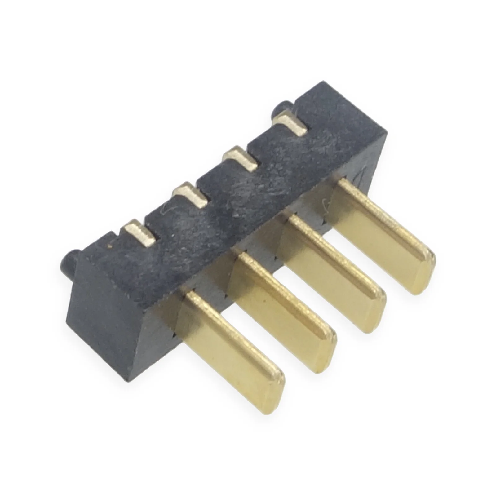 KS-2.5-M-VSMTPOST · 4P
Generic device illustration + real Kangsheng contact structure
A fixed register may use an adapter throughout operation. A portable terminal may combine a battery and receipt printer. Record current, duration and permitted voltage drop during printing as a separate duty.
02 / FROM MOTION TO CONTACT
Turn device motion into mounting conditions.
Sliding a battery into rails, closing a battery cover and seating a device in a cradle create different motion paths. Put the insertion direction, contact-loading direction and PCB normal on a section view. Locate the latch or hard stop on that same view. The enclosure, guides and board support establish the load path; the contacts meet their counterpart at the final position.
For a battery bay, provide the counterpart contact-plane height and lateral offset. For a cradle, add the entry angle, guide clearances and device centre of gravity. Follow the relative motion from first contact to the seated stop, including removal. Give insertion forces a defined mechanical path through the assembly rather than leaving the solder pads to locate the device.
In a multi-slot charger, separate the individual slot interface from the overall power distribution. List charging and communication nets per slot, the number of slots operating together, the shared supply and return, and the thermal setup. Matching contact counts establish a position count; the rest of the interface still comes from the mating drawings and circuit brief.
04 / SPRING-CONTACT POSITION
Side-press: the contact plane. Top-press: the assembly height.
The BC75 540 and 650 have housing heights of 5.4 and 6.5 mm. Nominal compression is 1.35 mm (1.85 mm free projection − 0.50 mm working-position offset). Add battery, PCB, enclosure and stop tolerances to the same assembly stack.
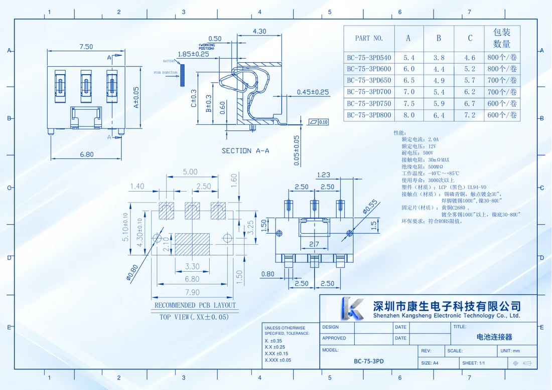
View dimension detail
Free projection: 1.85 ± 0.25 mm; working-position dimension: 0.50 mm.
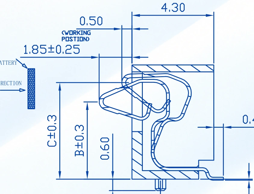
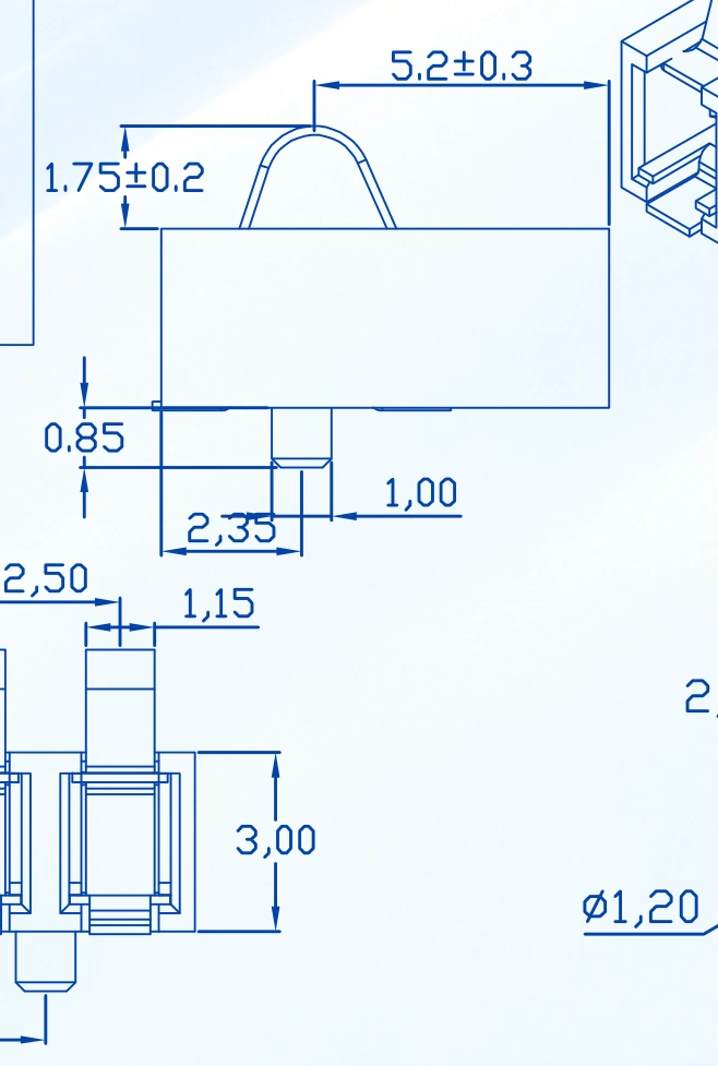
The BC82-4PD300 has a 3.00 mm housing and 1.75 ± 0.2 mm free projection. Send the assembled PCB-to-battery contact-plane distance, stop and tolerance range so we can confirm compression against your structure.
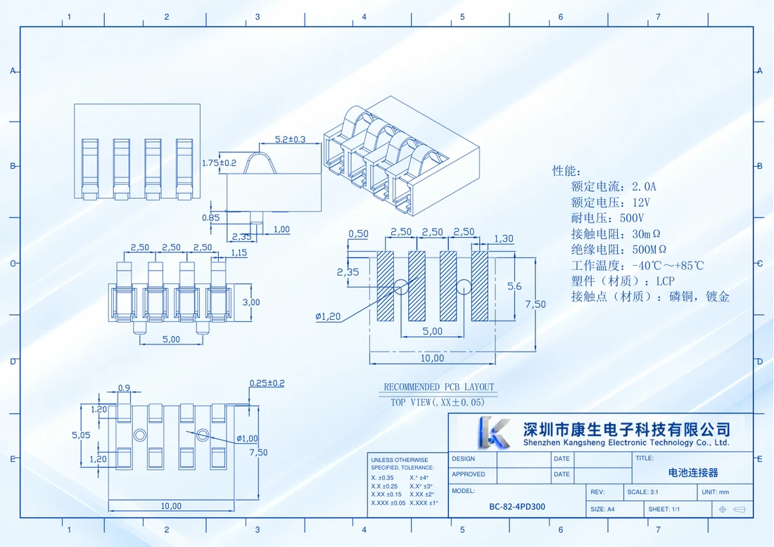
View dimension detail
Housing height: 3.00 mm; free projection: 1.75 ± 0.20 mm.
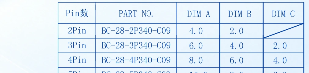
For the BC28 C09 series, use the four-contact row: 2.00 mm pitch, 3.40 mm housing and A/B/C dimensions of 8.0/6.0/4.0 mm. Mark the actual distance between the two contact planes, the stop and their tolerances on the assembly section, then check the envelope with the 4P STEP.
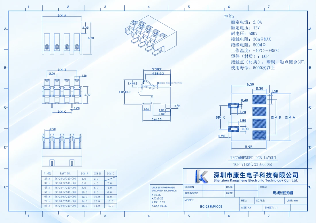
View dimension detail
4Pin row: A / B / C = 8.0 / 6.0 / 4.0 mm.
Scroll across the complete variant row.
05 / CHECK BOTH HALVES
Blade interfaces: compare SMT male and through-hole female mounting.
The four-position male reference has SMT tails and locating posts. The selected BL352 female has right-angle through-hole tails and square posts. Their board-side footprints, edge clearances and support arrangements are different. Place each PCB view in its own assembly, then compare the mating views from a stated direction.
The male drawing states 5 A / 30 V AC. The female drawing states 7 A and 10 A momentary; its 500 V entry is dielectric withstand. Put continuous current, peak amplitude and duration in the load brief, then check the current path through the contacts and board terminations.
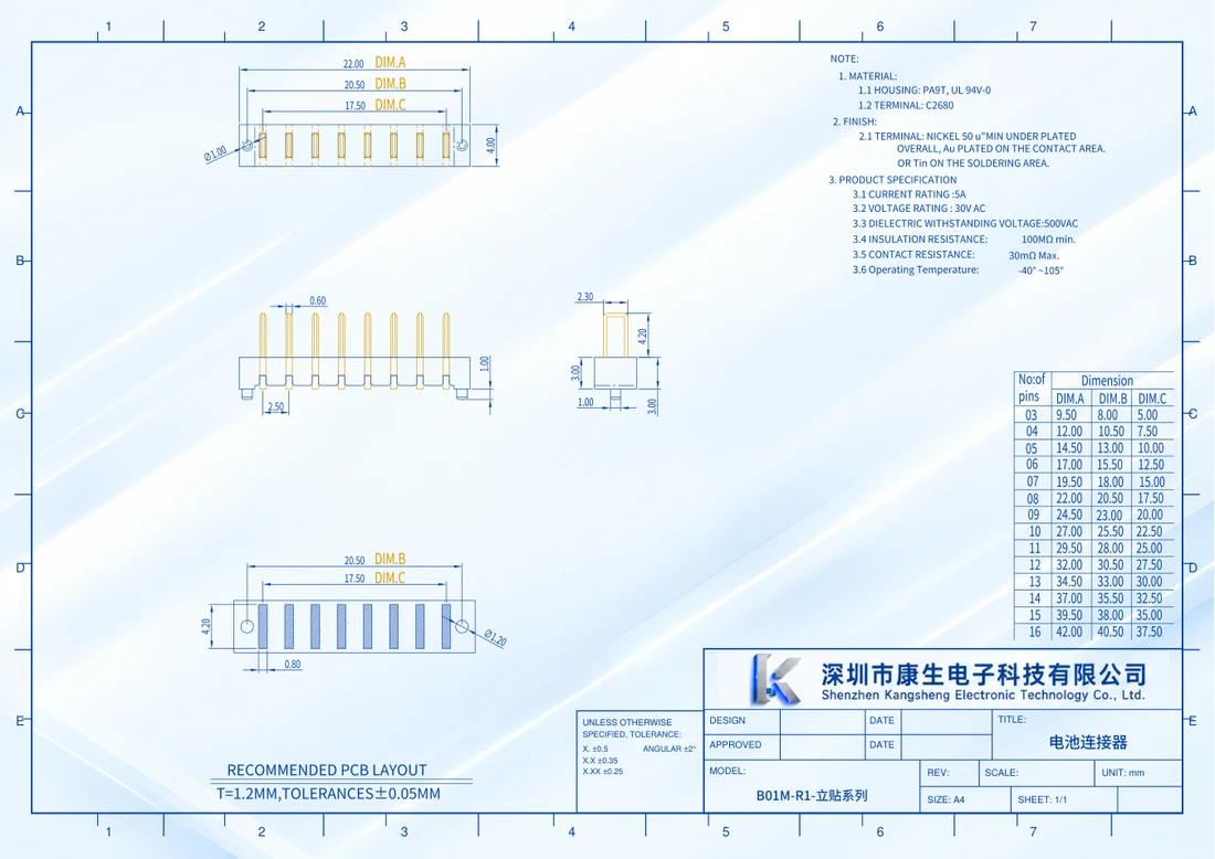
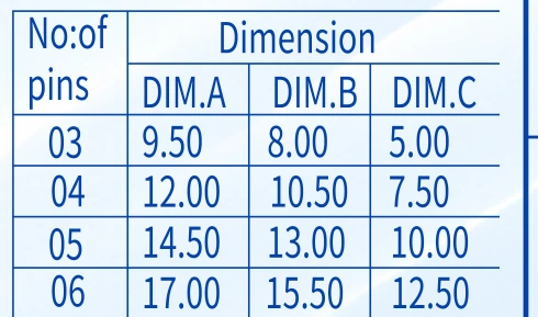
View dimension detail
04-position row: A / B / C = 12.00 / 10.50 / 7.50 mm.
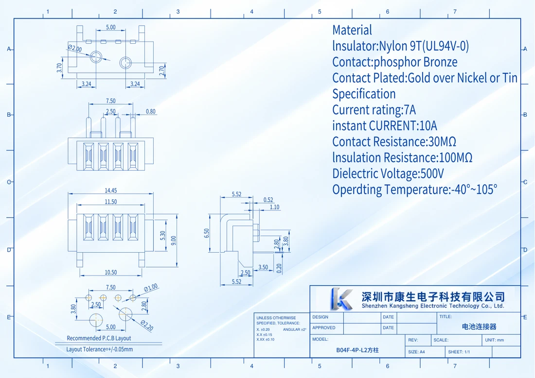
View dimension detail
Four-contact center span: 7.50 mm; adjacent pitch: 2.50 mm.
06 / SPECIFY THE DUTY
For a printing POS, list the printing duty.
For a fixed register, start with the adapter input and board-side path. For a portable POS, identify whether the battery is user-removable, service-removable or fixed, then mark the battery-to-board and terminal-to-cradle contact locations.
For a terminal with a printer, list the operating modes that matter: starting a print, sustained printing and printing while charging, where applicable. For each mode give peak amplitude, duration, repetition and the minimum acceptable supply voltage. Add simultaneously loaded contacts, conductor or trace dimensions, ambient temperature and allowed temperature rise.
Number supply, return, temperature sensing, identification and communication nets. Mark both halves from the same viewing direction, and record the load waveform and temperatures during sample checks so electrical and mechanical reviewers use the same interface brief.
| Input | What to provide | What it resolves |
|---|---|---|
| Interface location | Battery bay / device cradle / fixed input | Defines which connection is being selected |
| Load waveform | Continuous current, peak, duration, repetition and allowed drop | Lists the load for printing and charging modes |
| Mechanical stack | Contact plane, guides, stop and board support | Defines the loaded position and force path |
| Validation conditions | Temperature, dust, cleaning, cycle target and sample quantity | Builds a specific sample evaluation plan |
07 / A LAYOUT-SPECIFIC OPTION
Consider a mixed layout when the interface needs it.
The KS-HC-11M male and KS-HC-11F female use a 2 + 7 + 2 layout: four large outer contacts and seven smaller central contacts, at mixed 2.0 / 5.0 mm pitch. Start with the envelope and numbered nets to decide whether the assembly needs this wider format.
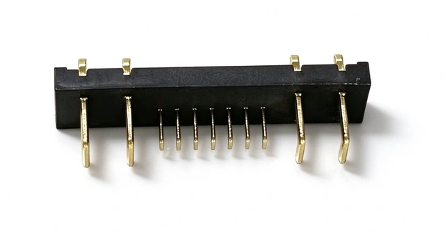
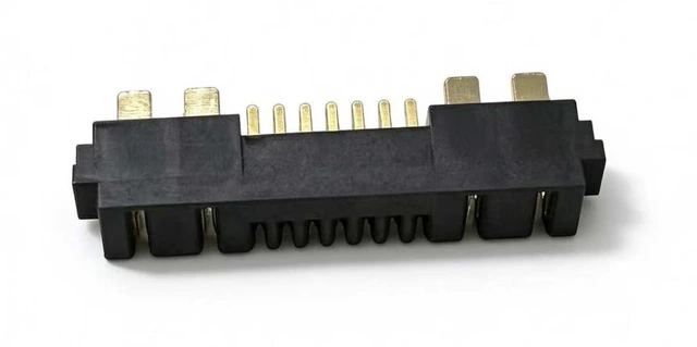
The KS-HC-11F female PDF states 25 A rated and 30 A momentary for each large contact. The download links provide male and female 2D DWG drawings. For a compact device, compare the smaller interfaces first, then check the 11PIN layout when more power and signal contacts are needed.
08 / BEFORE SAMPLES
Resolve these questions before selecting samples.
Does a wired scanner need a battery connector?
Check the power architecture. A wired scanner can take power through its host cable, making the cable entry and board connection the relevant interfaces. Assess battery or cradle contacts where those connections actually exist.
Can a battery bay and charging cradle share one brief?
Mark each interface in the brief. For the bay, include the battery contact plane and latched stack. For the cradle, add the device entry path, guides, stop, net assignments and use cycles.
How is BC82 compression set in the assembly?
BC82 compression is set from your assembly dimensions. Send the distance from the PCB to the battery contact plane, the stop and tolerance range, and we will confirm it against your structure.
Do four contacts at 2.5 mm pitch establish a mating pair?
Compare both complete drawings: blade width and thickness, cavity entry, keying, orientation, numbering and engagement depth. The male SMT and four-contact BL352 female rows keep their own drawing values.
What current should a printing POS brief specify?
Use the device measurements or design load table. Specify continuous current, printing peak amplitude and duration, repetition and allowed voltage drop, including whether charging and printing operate together.
What files start a useful sample discussion?
Send device type, interface location, both mating views or sections, board space, pinout, electrical duty, solder process, sample quantity and expected usage. Select the exact contact-count and tail variant within a series; housing height can be discussed around the PCB space.
What Kangsheng can provide
Download drawings and available STEP models directly.
Housing height can be customized for your PCB layout.
Samples are available for assembly checks.
YOUR NEXT INTERFACE
Send the interface drawing. Start with the actual structure.
Tell us where the interface sits, how the two sides move, the available PCB space and continuous or peak loads. Include pinout, mounting process, sample quantity and expected usage for a focused drawing discussion.
Discuss your interface