
ASSEMBLY & SELECTION GUIDE
Top-Press vs Side-Press Spring Battery Connectors: Read the Contact Direction in the Drawing
Read contact direction, PCB references and working-position labels in Kangsheng BC75 and BC82 drawings before choosing the assembly path.
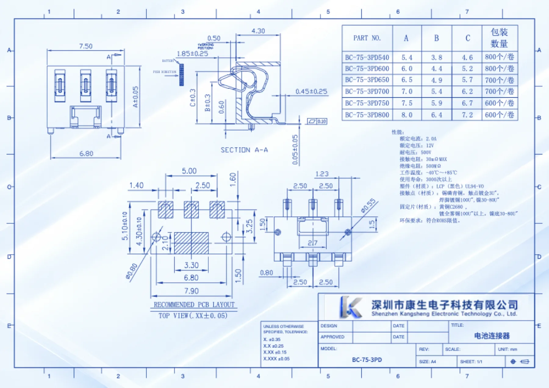
Top-press and side-press describe the direction in which the mating surface loads a spring contact. They do not, by themselves, describe how a battery slides into a device. To compare a PCB-mounted connector, identify the board reference, the contact surface and the working position in its drawing before choosing the assembly path.
Kangsheng's BC-82-3PD550 and BC-75-3PD650 provide a useful drawing exercise. Both product records specify three contacts at 2.5 mm pitch. The first is listed as top-press; the second as side-press. Their drawings show different contact arrangements, so matching pitch and pin count is only the beginning of the comparison.
For either direction, calculate spring-contact compression from a common datum before selecting the installed position.
Start with the board reference, rather than the screen orientation
A rotated PDF can make a side contact appear to point upwards. Find the soldering features and the recommended PCB layout first. Use the board surface as the reference plane, then look at the section or side view to locate the contact face relative to it.
In the BC-75-3PD series sheet, SECTION A–A shows the soldering features at the bottom and the battery contact at the side. The drawing labels both PUSH DIRECTION and WORKING POSITION beside that contact. This is the useful evidence for the side-press description. It is more specific than the direction in which a photograph happened to be taken.
Figure 1. Original Kangsheng series drawing. Follow the push-direction arrow in SECTION A–A and keep the model table visible. The drawing is a geometry source, not a report of an assembly test. Open the original BC-75 series PDF.
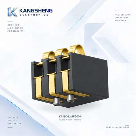
The BC-82-3PD550 side view shows the curved spring contact above the housing, while the board connection and locating features are below it. Its product record identifies this arrangement as top-press. Use the side and isometric views together to identify the exposed contact surface; the housing outline alone does not describe its operating position.
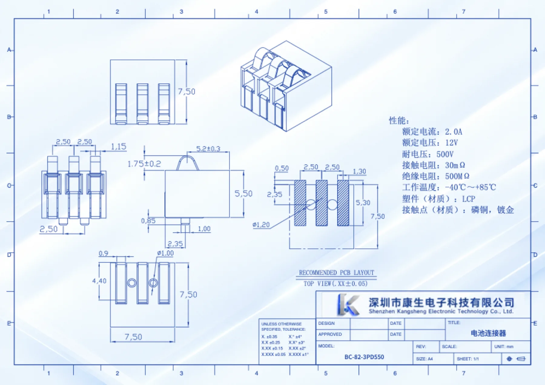
Figure 2. Original BC-82-3PD550 drawing. The 5.50 housing dimension and the spring profile belong to different features. Read their arrows separately. Open the original BC-82-3PD550 PDF.
Separate three directions in the assembly discussion
An assembly review needs three descriptions: how the contact is loaded, how the battery or mating part moves into place, and how the connector is placed and soldered on the board.
These descriptions can be different. For example, a designer may propose sliding a battery into a housing and then securing it against a spring contact. That is an assembly proposal, not an established application for either Kangsheng part in this article. Its final contact loading direction still needs to be shown in the assembly drawing.
Mark the moving component, the final contact face and the available approach space. If the contact rubs along another surface during insertion, show that path as well. A connector's category name cannot answer whether a particular enclosure guides the part onto the intended surface or exposes it to an unintended load.
This distinction also makes a supplier question easier to answer. “The battery enters from the left” describes an insertion path. “The mating pad finishes at this coordinate and presses in this direction” describes the contact condition that needs review.
Housing height is one input; working position is another
The BC-75 table lists A=5.4 for BC-75-3PD540 and A=6.5 for BC-75-3PD650. Those two listed A values differ by 1.1 mm. The same sheet separately labels the side contact's working position and a 0.50 dimension in that region. The vertical A difference is therefore not a value to enter automatically as horizontal compression or permitted travel.
For BC-82-3PD550, the product record lists a 5.5 mm housing height. Use the corresponding drawing to identify the spring profile and the board reference. The product page's housing-height field does not establish the complete operating window of the contact.
When preparing the assembly, record housing clearance, free contact location and intended mating-surface position separately. Ask for the allowable operating range and its reference before approving a tolerance calculation. A nominal position on a drawing and a maximum safe travel are different inputs.
The existing BC-75 height and drawing guide covers the 540 and 650 model rows in detail. Use it for that height decision rather than treating this direction comparison as another variant-selection table.
Do not turn this into a one-variable performance comparison
BC-75-3PD650 and BC-82-3PD550 share a listed pitch and pin count, but their contact arrangement, housing geometry and board features differ. The available documents do not establish a controlled comparison of contact force, temperature rise, vibration resistance or service life between them.
Choose the arrangement around the actual interface and the documented operating conditions. If a project needs a performance comparison, give the supplier the load, environment, mating surface and acceptance criteria. A photograph, a CAD model or a shared pitch cannot replace those conditions.
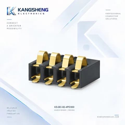
The four-contact BC-82-4PD300 illustrates another boundary: its product record lists four pins and a 3 mm housing height. It is not a three-pin counterpart with only a lower housing.
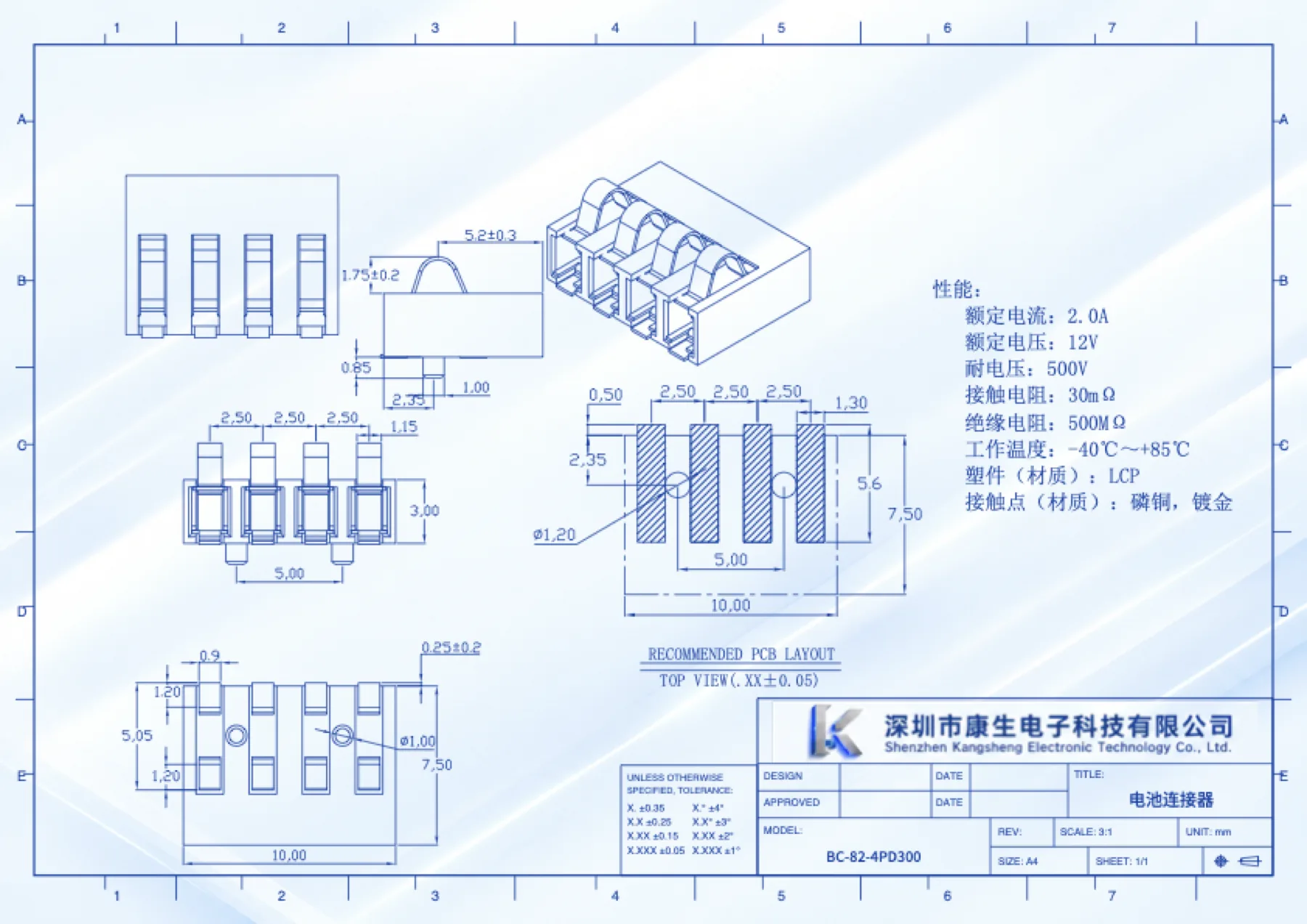
Figure 3. Original BC-82-4PD300 drawing. Keep the exact model and pin count with the drawing. The BC-82 model guide explains that separate variant comparison. Open the original BC-82-4PD300 PDF.
Make the next enquiry specific
For the board-pattern details, use the PCB footprint reference-view guide alongside the contact-direction drawing.
For a direction review, send the complete connector part number and a section of the assembly showing the board plane, mating pad, final position and insertion path. Include the project pinout and the conditions for any requested electrical or mechanical evaluation.
Use the exact model's files: BC-75-3PD650 has its own STEP file, while BC-82-3PD550 has its own PDF and CAD file. A series name on an email is less useful than a filename, a model row and a marked contact surface.
Explore the spring battery connector range when choosing the initial geometry. Then send the model and marked assembly references with your enquiry so procurement and engineering can discuss the same interface.
Source: Kangsheng Electronics product records and original BC75/BC82 drawings.
The battery-pack insertion and contact-loading guide shows how tool-pack motion, the final stop and contact direction become separate drawing inputs.
CATALOGUE REFERENCES
Related products

YOUR NEXT DESIGN CHECK
Review your PCB footprint.
Send the selected part drawing, pin reference and PCB constraints for a mounting review.
Ask about this article