
ASSEMBLY & SELECTION GUIDE
Robot Vacuum & Cleaning Equipment Battery Connector Selection: High-Current Temperature Rise, Blade Receptacle Mating, and Anti-Vibration Tolerances
System-level connector guide for robot vacuums and commercial floor scrubbers (4S Li-ion): 25A surge temperature rise (ΔT<30K), power/BMS signal isolation, blade mating depth, and shock tolerance.
Robot vacuums and commercial floor-cleaning machinery (floor scrubbers, autonomous sweeper-mops, and docking stations) are rapidly transitioning from light-duty surface sweeping toward high-pressure suction, automated mopping, and demanding obstacle-clearing regimes. Their internal battery management systems (BMS) and mainboard drive links face intense physical and electrical stresses: surge current spikes, sensitive multi-signal isolation, high-frequency motor vibration, and constrained enclosure geometries.
In a standard 4S lithium-ion architecture (14.4 V nominal, 16.8 V peak, 12.0 V discharge cutoff), the core engineering priority is clear: the primary power bus must safely handle up to 25 A instantaneous stall and climbing currents with a contact temperature rise strictly below 30 K, while high-current lines remain physically isolated from low-voltage BMS communication lines (I2C/SMBus/NTC) to eliminate inductive spikes and vibration-induced false cutoff trips.
Drawing upon real-world production cases with top-tier robotic cleaning OEMs, Kangsheng's engineering team provides an in-depth breakdown of battery connector selection across system architecture, contact physics, mating tolerance stacks, and field failure countermeasures.
1. System Architecture & Power Topology: Physical Isolation of Power and Signal
The powertrain of an autonomous robot vacuum comprises dual brushless drive wheels, high-RPM vacuum turbine motors (often exceeding 100,000 RPM), roller and side brush motors, pumps, and LiDAR sensors. While continuous steady-state current runs between 4 A and 8 A, momentary surges climb to 18 A through 25 A during heavy rug traversal, obstacle-clearing wheel stall, brush entanglement, or max-suction boost mode (pulse durations ranging from 200 ms to 3 seconds).
Within the same battery pack enclosure, the BMS must reliably transmit cell voltage telemetry, charge/discharge state indicators, gas-gauge register communications (I2C or SMBus), and analog NTC thermistor sensing signals back to the main processor.
If engineers route power and signals on uniform-pitch pin headers, high-frequency PWM switching transients from the motor drive stage can induce severe electromagnetic interference (EMI) and voltage spikes on adjacent signal lines. Worse, localized joule heating on power pins can conduct directly into nearby NTC terminals, triggering premature thermal shutdown errors.
Robot vacuum battery interconnects must adhere to two architectural imperatives:
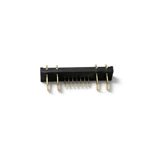
- Variable-Pitch Physical Isolation: Power pins and signal pins must be segregated with non-uniform pitch spacing. High-power terminals should maintain $\ge 5.0\text{ mm}$ center-to-center clearance to provide generous creepage and air gap clearances; low-voltage signals can utilize compact $2.0\text{ mm}$ spacing. A prime example is Kangsheng's custom KS-HC-11M / KS-HC-11F 11PIN Hybrid Connector, featuring 4 heavy-current blade positions flanking 7 central signal positions separated by thick insulating dielectric barriers.
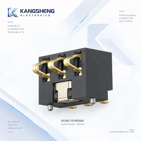
- Dedicated Interface Splitting: Internal power pack interfaces (demanding high mechanical retention, keying, and positive locking) must be physically separated from external automatic docking station contacts (requiring low insertion force, large lead-in alignment tolerance, and wiping action). Use keyed male/female blade headers inside the chassis, and specialized high-deflection spring contacts (such as the KS-BC-75-3PD540) for external charging pads.
2. Head-to-Head Architecture Comparison Table
Three primary connector approaches dominate autonomous floor-care equipment. The table below compares their core engineering specifications:
| Evaluation Dimension | Hybrid High-Current Header (e.g., KS-HC-11PIN) | Modular Blade Receptacle (e.g., KS-BL-352) | Surface-Mount Spring Contact (e.g., KS-BC-82 / BC-75) |
|---|---|---|---|
| Continuous Current Rating | Power pins: 25 A (30 A peak) / Signal: 2 A | 7 A per blade (up to 14–20 A in parallel) | 2.0 A per contact (up to 6–8 A in parallel) |
| Mating Mechanism | 11-pin polarized male-female insertion | Right-angle / vertical blade docking | Single or dual compression wiping |
| Contact Resistance | Power: $\le 10\text{ m}\Omega$; Signal: $\le 30\text{ m}\Omega$ | Single blade: $\le 20\text{ m}\Omega$ | Loaded working position: $\le 30\text{ m}\Omega$ |
| Shear Stress Resistance | Exceptional (reinforced PA9T body + side locks) | High (dual molded PCB posts absorb shear load) | Moderate (relies on chassis mechanical stops) |
| Footprint / Profile | 38.7 × 7.67 mm; vertical or right-angle | 2.50 mm pitch compact layout | Ultra-low profile (3.0 mm to 5.4 mm height) |
| Target Application | Flagship vacuum modular battery pack interfaces | Compact scrubbers & internal sub-pack wire boards | Auto-docking charging pads, side-docking contacts |
3. Contact Physics: Temperature Rise Limits, Constriction Resistance, and Stress Relaxation
Robot vacuum battery compartments are tightly enclosed near drive wheels and vacuum chambers with minimal airflow. Connector overheating degrades the plastic resin housing, accelerates contact oxidation, and poses thermal risks to adjacent lithium cells.
3.1 Joule Heating and Temperature Rise Modeling
Thermal dissipation in terminal interfaces stems from contact and bulk bulk resistance: $P = I^2 \cdot R_{contact}$
Under Holm electric contact theory, true electrical contact occurs only across microscopic surface asperities forming conducting "A-spots": $R_c = \frac{\rho}{2 \cdot n \cdot a}$
Where $\rho$ is material resistivity, $n$ is asperity spot count, and $a$ is average spot radius. Inadequate normal force shrinks the effective conducting area, triggering exponential spikes in constriction resistance and severe localized heat dissipation.
Engineering Temperature Rise Standard: Under rated steady-state current (e.g., 8 A continuous for 2 hours), contact temperature rise $\Delta T$ must remain strictly below $30\text{ K}$ (ensuring terminal surface temperatures stay below $55^\circ\text{C}$ at $25^\circ\text{C}$ ambient). During transient $25\text{ A}$ surges (3 seconds duration), the rapid temperature rise must not exceed $\le 15\text{ K}$.
3.2 Terminal Material Selection and Plating Integrity
To maintain low electrical resistance and mechanical spring retention over thousands of operational hours:
- High-Conductivity Phosphor Bronze Alloys: Power receptacles must use premium phosphor bronze (such as C5191 or C5210, conductivity $\ge 13\%\text{ IACS}$) or beryllium copper. Standard brass terminals exposed to continuous $80^\circ\text{C}$ enclosure ambient heat suffer severe stress relaxation, losing more than 30% of their normal contact force after 1,000 hours, causing thermal runaway.
- Gold-over-Nickel Anti-Fretting Plating: Contact surfaces require nickel-underplated gold (minimum $1.27\ \mu\text{m}$ Ni base, $\ge 3\ \mu\text{''}$ hard gold on contact interface). Tin plating fails rapidly under robot motor vibrations: micro-motion causes fretting corrosion, generating non-conductive tin oxide debris that drives contact resistance from milliohms into the multi-ohm range, causing abrupt drive motor shutdown.
- High-Temperature UL94 V-0 Resins: Connector insulators must be molded from high-performance engineering thermoplastics like PA9T or LCP with deflection temperatures exceeding $260^\circ\text{C}$, eliminating pin displacement during SMT reflow or extreme thermal events.
4. Blade Receptacle Mating Depth and Tolerance Stacking
During battery pack swapping or automated factory assembly, mechanical alignment tolerances directly dictate electrical reliability.
Taking Kangsheng's KS-2.5-M-VSMTPOST Vertical Blade Header paired with the KS-BL-352 Right-Angle Receptacle as an engineering benchmark, hardware designers must audit several tolerance dimensions:
- Effective Mating Wipe Depth:
Nominal male blade insertion into the dual-beam female contact spans $4.0\text{ mm}$ to $4.8\text{ mm}$. After factoring in tooling tolerances, pack latch play, and shock displacement, minimum dynamic wipe depth must remain $\ge 2.2\text{ mm}$. Falling below this safety threshold leaves contacts on the brink of disengagement during step drop impacts.
- Lead-in Chamfers and Self-Centering Geometry:
Male blades require generous dual-sided $15^\circ$ to $30^\circ$ lead-in chamfers, complemented by $\ge 0.8\text{ mm}$ funnel lead-in flares on female housing apertures. This allows smooth blind mating even when packs enter with $\pm 1.0\text{ mm}$ lateral offset or up to $\pm 3^\circ$ angular tilt, preventing bent terminal tabs.
- Molded Locating Posts for SMT Shear Protection:
Robot vacuum battery packs weigh between 300g and 600g. When dropped over a 20 mm ledge or subjected to forceful pack insertion, lateral shear forces readily exceed 40 N. If surface-mount connectors rely solely on solder fillets to anchor the component, PCB copper pads can shear off completely. Kangsheng vertical and right-angle headers feature precision integrated locating posts (Diameter $1.20 \pm 0.05\text{ mm}$) that engage snugly into host PCB mounting holes, routing over 85% of mechanical shock directly into the board substrate.
5. Typical Field Failure Modes and Checklist
Key failure modes observed in volume robotic cleaning deployments and their mitigation strategies:
- Failure Mode 1: Contact Arcing and Carbonization during Mating
- Root Cause: Unbuffered mainboard bus capacitance creates high inrush current, or hot-plugging occurs under active load.
- Countermeasure: Employ "make-first-break-last" pin sequencing (available on custom 11PIN hybrid connectors) to ground the system before power lines engage, and add NTC inrush limiters or soft-start FET control on the mainboard.
- Failure Mode 2: Contact Fatigue and Permanent Plastic Deformation
- Root Cause: Excessive compression travel forced by pack latches exceeding the contact's elastic limit.
- Countermeasure: Design nominal travel within the 40% to 60% golden compression window (e.g., 1.0 mm to 1.2 mm loaded height on a 2.0 mm total travel spring), and integrate rigid chassis hard stops.
- Failure Mode 3: Charging Dock Intermittent Disconnection
- Root Cause: External charging contacts suffer oxidation from dirty mop water and cleaning detergents, while pure vertical top-press contacts lack self-cleaning wiping action.
- Countermeasure: Switch to side-press or angled spring contacts (such as the KS-BC-75-3PD540) that deliver $0.35\text{ mm}$ of lateral wipe upon entry, and specify thick gold plating ($\ge 5\ \mu\text{''}$).
- Failure Mode 4: Reflow Coplanarity Defects and Solder Bridging
- Root Cause: Thin plastic housings bow under reflow heat, exceeding $0.10\text{ mm}$ terminal coplanarity limits.
- Countermeasure: Choose moisture-resistant PA9T / LCP formulations delivered in sealed Tape & Reel packaging, strictly adhering to factory MSL staging guidelines.
6. Recommended Kangsheng Robot Vacuum Battery Connector Parts & Drawings
The following production-proven parts are widely deployed in commercial and residential cleaning robots:
- Specs: 4 high-current blade positions (25 A rated, 30 A peak) + 7 signal positions (2 A rated); PA9T high-temp resin, UL94 V-0.
- Applications: Flagship autonomous sweeper battery packs, heavy-duty floor scrubber power links.
- Engineering Assets: Contact sales for 2D engineering drawings and STEP 3D models.
- Specs: 4-position · 2.50 mm pitch · 90° through-hole mating; 7 A continuous, 10 A peak; 500 V withstand.
- Applications: Compact 4S lithium battery sub-pack board-to-wire connections.
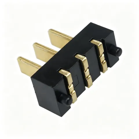
- Specs: 2.50 mm pitch vertical SMT · 0.60 mm high-conductivity copper blades with integrated alignment posts.
- Applications: Board-mount male docking header resisting high shear loads.
- Specs: 3 contacts · 2.50 mm pitch · 5.4 mm housing height; nominal 1.35 mm working compression with wiping action.
- Applications: Autonomous docking recharge pads and anti-drop ground reference contacts.
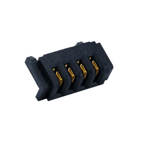
- Specs: 4 contacts · 2.50 mm pitch · 3.00 mm ultra-low profile; 1.75 mm free height.
- Applications: Compact internal module power taps and sensor board interfaces.
For detailed drawings and technical datasheets, visit our dedicated Robot Vacuum & Cleaning Equipment Connector Selection Center.
7. Robot Vacuum Battery Connector Engineering FAQs
Q1: Why must robot vacuum 4S lithium battery systems specify 25A momentary surge ratings?
A: While average continuous current during uniform floor sweeping ranges from 3 A to 6 A (at nominal 14.4 V), current spikes dramatically whenever the vacuum encounters high-pile rugs, overcomes 20 mm door thresholds, throttles vacuum suction up to 8,000 Pa, or roller brushes stall on cords. These pulse surges reach 18 A to 25 A in milliseconds. If contacts lack adequate thermal mass and normal force, localized contact overheating causes pitting, arcing, or catastrophic terminal fusion.
Q2: How do engineers optimize blade header mating insertion and extraction force?
A: Normal target insertion force ranges between $1.5\text{ N}$ and $3.5\text{ N}$ per blade, with terminal contact normal force maintained at $\ge 1.0\text{ N}$. For a 4-pin blade header, total assembly insertion force should register around $8\text{ N}$ to $14\text{ N}$, with retention force exceeding $\ge 6\text{ N}$. Excessive insertion force leads to assembly pin bending; insufficient force undermines dynamic contact resistance stability under vibration.
Q3: Should robot vacuum battery interfaces specify gold or tin plating?
A: Gold plating is strongly advised for all power and signal contacts (minimum $1.27\ \mu\text{m}$ nickel base with $\ge 3\ \mu\text{''}$ gold on contact points). The constant high-frequency vibration generated by drive motors and vacuum turbines triggers fretting micro-motion. Tin plating rapidly oxidizes into non-conductive debris under micro-motion, driving contact resistance up by tenfold within hundreds of operating cycles. Gold maintains an inert, low-resistance interface across thousands of hours.
Q4: How can designers prevent SMT solder pad peeling during battery pack swapping?
A: First, always specify connectors with molded locating posts (such as KS-2.5-M-VSMTPOST) that penetrate through-holes in the PCB to absorb lateral mechanical shear. Second, connect side solder retention tabs (fitting nails) to expansive ground copper pours stitched with thermal vias. Finally, mold guiding rails into the vacuum chassis to restrict angular battery pack insertion.
Q5: What causes charging dock contact failure, and how does proper component selection solve it?
A: Docking pad failures are primarily caused by liquid detergent film accumulation and slight docking misalignment. Effective solutions include: 1. Replacing vertical compression pads with side-press spring contacts (such as KS-BC-75-3PD540) that execute a $0.35\text{ mm}$ mechanical wiping motion upon entry to clear oxidation; 2. Designing mechanical dock funnels that constrain docking tolerance within $\pm 1.5\text{ mm}$; and 3. Upgrading contact plating to heavy gold ($\ge 5\ \mu\text{''}$) to withstand corrosion from residual mopping water.
CATALOGUE REFERENCES
Related products
YOUR NEXT DESIGN CHECK
Send us your drawing.
We’ll check pitch, height and compression against your assembly requirements.
Ask about this article