
ASSEMBLY & SELECTION GUIDE
How to Choose Spring Battery Connectors: Pitch, Contact Style and Height
Pitch and pin count, top-press vs side-press, height and travel, and mounting: five points for choosing the right spring battery connector.
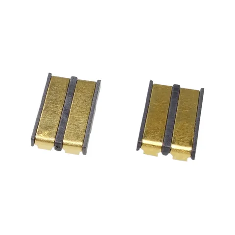
Spring battery connectors (also called battery contacts or battery spring terminals) sit between the battery and the PCB and keep contact through the spring force of their metal contacts. Here is what to check when choosing one.
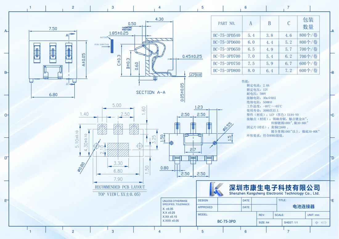
Use the selected part drawing to calculate minimum and maximum spring-contact compression.
1. Pitch and pin count
Pitch is the distance between the centres of two neighbouring contacts. Common values are 1.27, 2.0, 2.5, 3.0 and 4.0 mm. The pin count must match the battery contacts: usually positive and negative, plus signal pins such as temperature (NTC) or battery ID.
2. Contact style
- Top-press: the battery presses down onto the contacts. Compact, common in earbuds and watches.
- Side-press: the mating surface loads the spring contact from the side relative to the PCB. The battery's insertion path is a separate assembly condition.
- Plug-in: a male and female part mate together for a more stable connection with repeated mating.
Use the top-press vs side-press drawing guide to identify the board reference and contact-loading direction in the drawing.
3. Height and compression travel
Housing height sets how much space the connector takes inside the enclosure; compression travel sets the contact force after assembly. Too little travel risks intermittent contact, too much can fatigue the springs. Check the compressed height against your mechanical drawing.
4. Mounting
SMT suits automated assembly; through-hole is sturdier where there is more mechanical stress. Versions with locating posts align more accurately during placement and help carry side loads.
For a plug-in blade option, the 2.5 mm blade connector mounting guide separates SMT feet, through-hole tails and board support. Use the PCB footprint reference-view guide to check solder pads, locating holes and viewing direction separately from the component outline.
5. Check the drawing before ordering
Parts with the same pin count and pitch can differ in height and contact shape. Download the PDF drawing from the product page to confirm dimensions, and request samples to test in your device.
Can't find the right part? Send us your drawing or current part number and we will suggest a match.
CATALOGUE REFERENCES
Related products
YOUR NEXT DESIGN CHECK
Send us your drawing.
We’ll check pitch, height and compression against your assembly requirements.
Ask about this article