
ASSEMBLY & SELECTION GUIDE
Choosing 3-Pin, 4-Pin or 5-Pin Battery Connectors: Define the Pinout First
Choose 3-pin, 4-pin or 5-pin battery connectors by pinout, viewing direction and power and signal requirements. Do not guess temperature-sensing or communication connections from pin count.
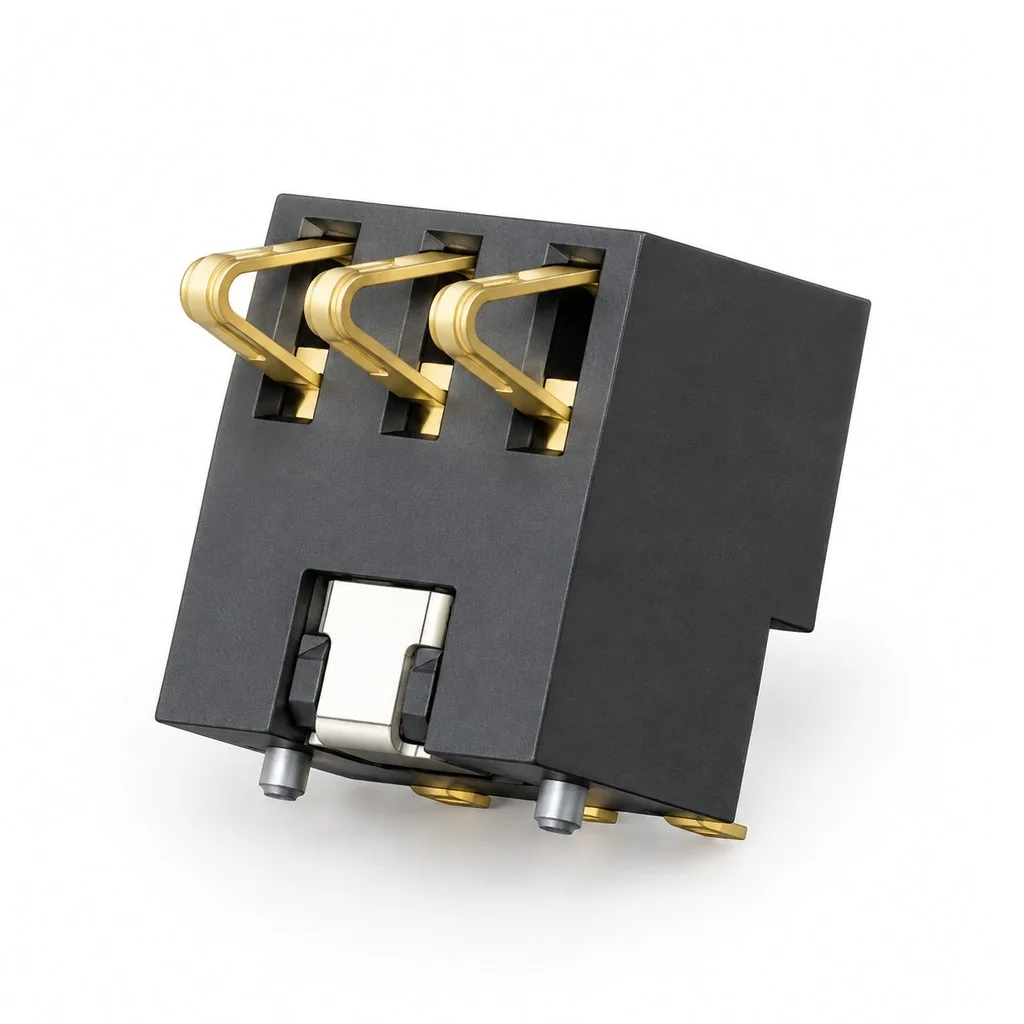
Before selecting a 3-pin, 4-pin or 5-pin battery connector, identify the circuits required at the battery interface, then filter mechanical options by pin count. Pin count describes the number of connection positions. It does not independently determine each pin's function, current or communication interface.
For a four-position blade candidate, add the 2.5 mm blade PCB footprint and mounting checks to the pinout review so the board-side view keeps the same pin reference.
Define the pinout before selecting a model
When reviewing a battery interface, first fix the viewing direction, for example “looking from the device side toward the battery contact face,” and mark pin 1 on the drawing. Then record each pin's function, connected circuit and electrical requirements. In addition to positive and negative terminals, a project may require temperature sensing, identification or communication. The actual assignments must come from the interface definitions for the specific battery pack and device.
A pinout table can include the following fields:
- Pin number and direction: mark them in the mating-face view and cross-check against the PCB view.
- Function and connection: power, return path or a specific signal, including where it connects.
- Electrical requirements: operating current, peak conditions or signal-interface requirements for that pin.
- Mechanical requirements: contact position, staggered pin lengths, empty positions or keying.
- Confirmation evidence: battery specification, schematic, drawing revision and responsible person.
Confirm unknown functions with the interface provider rather than filling gaps with assumptions about typical wiring. When changing battery suppliers, matching appearance does not replace a pinout check.
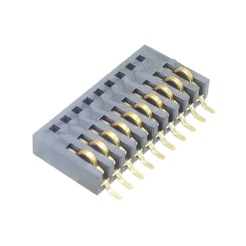
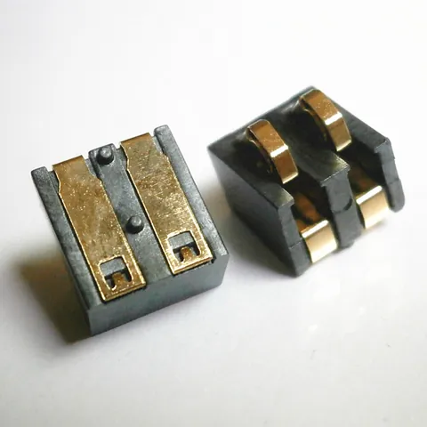
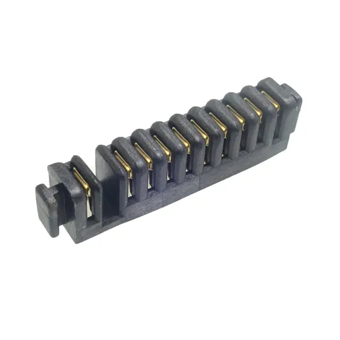
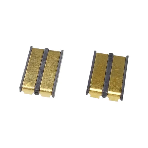
The following product-library images show three different models with three, four and five contact positions. They are not a set of interchangeable connectors with the same pitch, and no power, temperature-sensing or communication functions are assigned to the contacts.
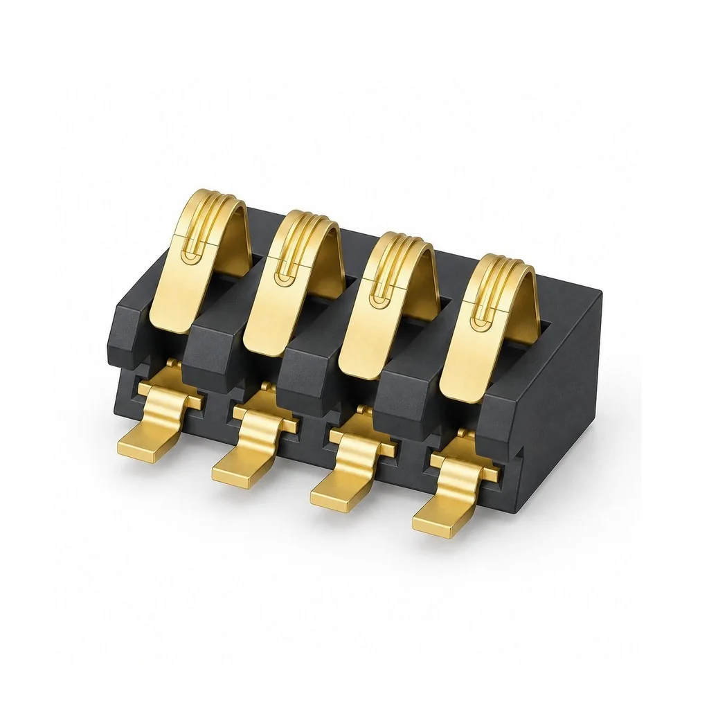
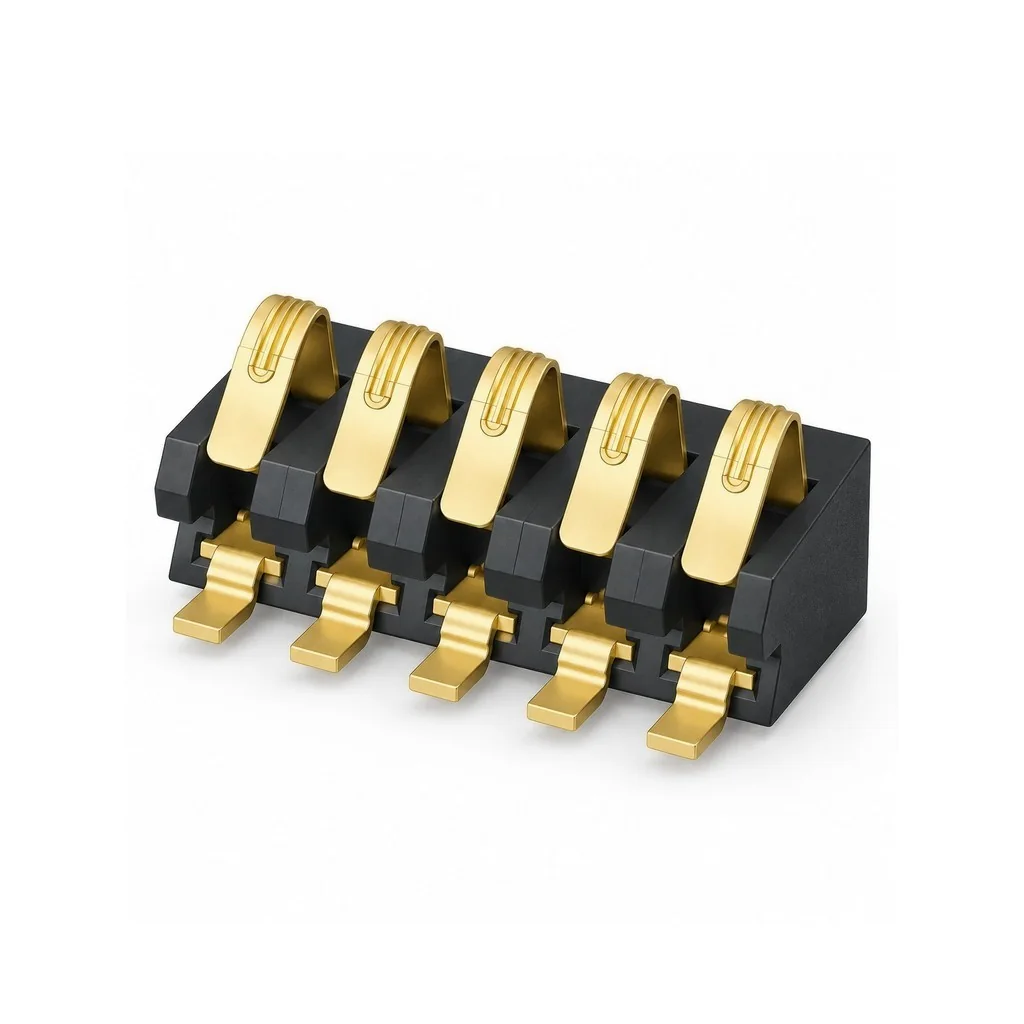
Use pin count to find Kangsheng candidates
The 2.5mm-pitch model page can support initial screening. For example, the public product pages list BC-35-3P550 as 3P top-press, BC-80-4PD300-2P as 4P top-press, and BC-15-NPD380 as 5P side-press. These examples show different pin counts and contact directions. Their published pin counts do not assign a common positive, negative, temperature-sensing or communication pinout to these products.
After identifying a candidate, check its contact direction, height, pads and mating-side layout against the design. Changing a 5P interface to 4P requires interface design work; it is not simply a matter of replacing the connector with one having fewer pins.
Evaluate power through multiple pins separately
TE's battery connector guidance warns that total current capacity cannot simply be calculated by multiplying the maximum current per contact by the number of contacts. Even when a design uses parallel pins, check the actual loaded contacts, return path, temperature rise and application conditions. Signal pins should not be counted as power-carrying capacity.
CATALOGUE REFERENCES
Related products
Frequently asked questions
Is the third pin of a 3-pin connector always for temperature sensing?
Can only two pins of a 5-pin connector be used?
Does a higher pin count mean higher current capacity?
YOUR NEXT DESIGN CHECK
Send us your drawing.
We’ll check pitch, height and compression against your assembly requirements.
Ask about this article