
ASSEMBLY & SELECTION GUIDE
2.5mm vs 2.54mm Battery Connector Pitch: Center Spacing and Overall Span
How can you distinguish 2.5mm from 2.54mm battery connector pitch? Check contact and solder-tail centers, first-to-last span, drawing units, viewing direction and supplier dimensions.
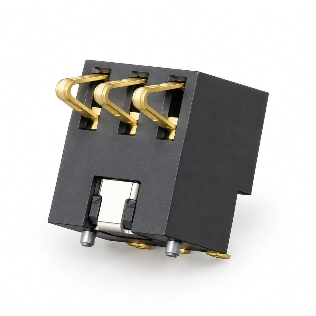
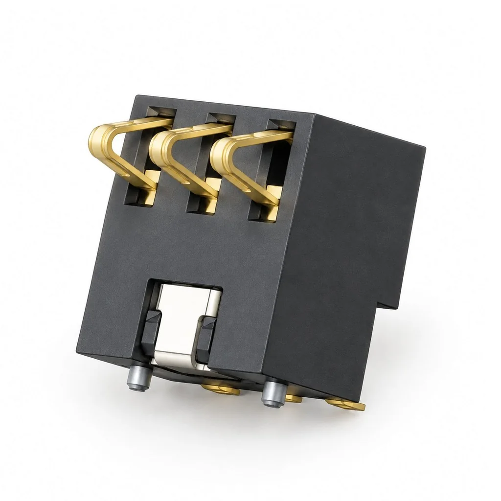
2.5mm and 2.54mm are different nominal pitches, with a difference of 0.04mm between adjacent positions. Start with the center spacing and units specified on the drawing, then check the measurement points. For a single row with equal spacing and no missing positions, the span between the first and last contact centers can help verify the pitch. A measurement that “looks about 2.5mm” should not be entered directly as a specification.
Which centers are being measured?
Pitch usually means the distance between adjacent position centers. Follow the dimension arrows on the drawing to identify the two reference lines: battery-side contact centers, PCB solder-tail centers or mounting-hole centers. The gap between terminal edges is not center spacing, and the plastic housing width cannot directly establish pin pitch.
After identifying the contact centers, follow the 2.5 mm blade PCB mounting checks to carry the selected tail and locating features into the footprint.
The contact side and board side of the same connector may have different pin layouts. If the drawing includes contact layouts, solder-tail layouts or multiple rows, record their dimensions separately. A 2.5mm dimension at one location does not establish the spacing everywhere.
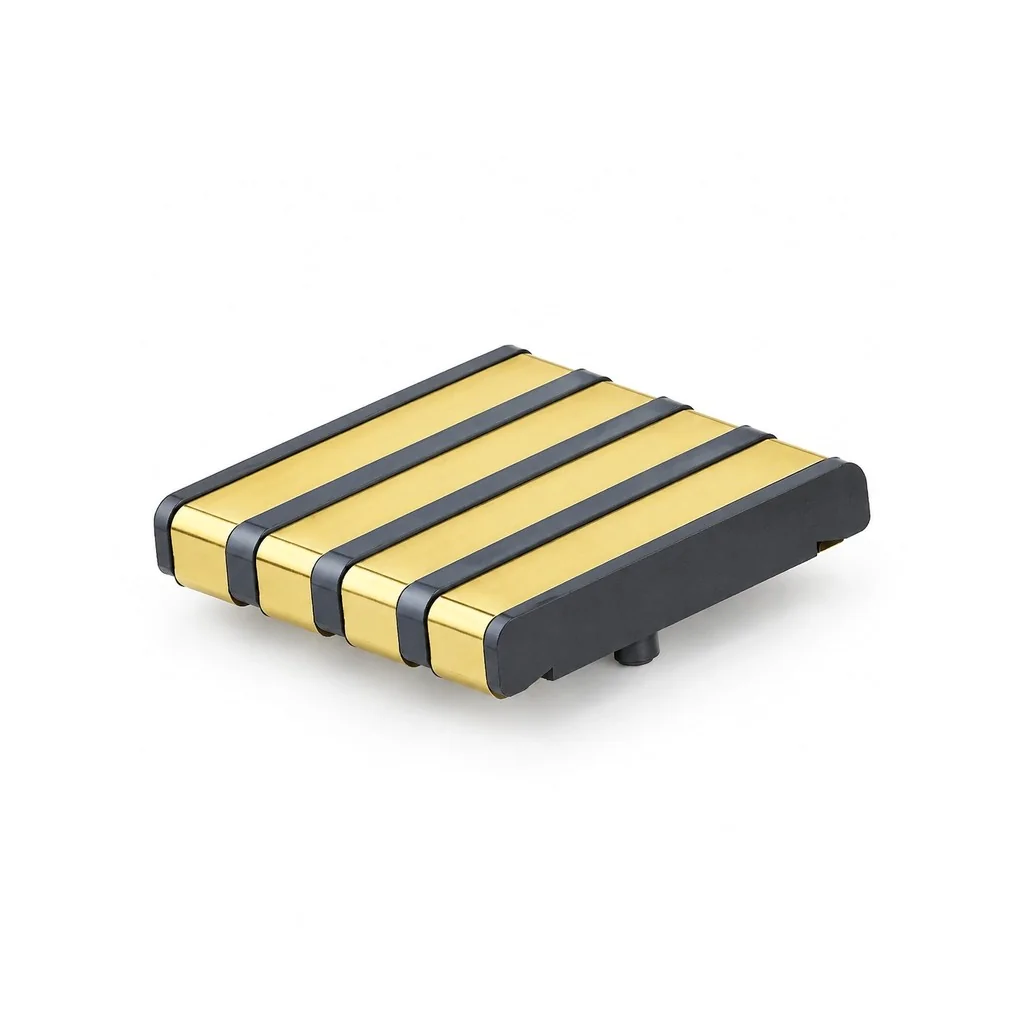
Verify pitch using the first-to-last span
For an N-pin connector with at least two pins in a single row, equal spacing and no missing positions, there are N−1 intervals between the first and last centers. The center-to-center span therefore equals pitch multiplied by the number of intervals. Dividing the span by the interval count can verify the pitch.
- 3P has two intervals: 2.5mm gives 5mm; 2.54mm gives 5.08mm.
- 5P has four intervals: 2.5mm gives 10mm; 2.54mm gives 10.16mm.
These are geometric calculations using nominal dimensions, not tolerances or acceptance limits for any model. With missing pins, mixed pitches or staggered layouts, do not simply subtract one from the visible pin count. First confirm the actual number of intervals crossed on the drawing. Measurement records should also identify the start point, end point and drawing view so the supplier can check the same distance.
Align the units and viewing reference
A drawing dimension of 0.100 inch corresponds to 2.54mm. For example, the official Samtec pitch catalog lists both units. This example explains the unit conversion; it does not establish the specification of a particular battery connector.
When comparing a paper drawing, PDF and sample, use the annotated dimensions rather than measuring a scaled screenshot. Specify whether the view is from the contact face, solder side or side, and mark pin 1 and the measurement direction. Sample measurements are an aid to identification. If the readings cannot clearly distinguish the two pitches, keep the original measurements and request drawing confirmation instead of assigning an allowable caliper error yourself.
What should you confirm with the supplier?
Send the complete model number, drawing revision and an image with the start and end points marked. Ask explicitly: “Is this the contact-side or solder-tail center spacing? Is the nominal value 2.5mm or 2.54mm, and where is its dimensional tolerance specified?” Include the pin count, row count and any missing positions so both parties check the same span.
Kangsheng's KS-BC-7-3PD600 publicly lists 3P and 2.5mm pitch. The 2.5mm-pitch model page can help identify candidates. Refer to the drawing for the specific model to confirm measurement references and tolerances.
CATALOGUE REFERENCES
Related products
Frequently asked questions
Does a measurement of approximately 2.5mm rule out 2.54mm?
Can the total width of a five-pin connector be divided by five?
What if the product title and drawing specify different pitches?
YOUR NEXT DESIGN CHECK
Send us your drawing.
We’ll check pitch, height and compression against your assembly requirements.
Ask about this article