
ASSEMBLY & SELECTION GUIDE
E-Bike and Energy Storage Blade Battery Connector Selection: Temperature Rise Safety Limits and Contact Plating Pull-Out Strength
Comprehensive engineering guide on high-current blade battery connectors for electric two-wheelers and energy storage: 20A–50A continuous current temperature rise (ΔT<30K), beryllium copper stress relaxation, silver plating, and pull-out retention mechanics.
In the powertrain architecture of electric two-wheelers (E-bikes, electric mopeds, e-motorcycles), light electric vehicles (LEVs), and portable power stations (solar generators), the primary battery interconnect channels the highest energy flux within the entire system. Driven by the mass adoption of 48 V, 60 V, and 72 V high-capacity lithium-ion pack platforms, battery connectors must withstand relentless combined stresses: heavy continuous current, steep hill-climbing current surges, road shock vibration, and thermal accumulation within unventilated battery enclosures.
Powertrain and battery packaging engineers confront two uncompromising electrical and mechanical criteria:
- Temperature Rise Safety Limits: Under continuous rated DC current loads (20 A to 40 A), terminal contact temperature rise must remain strictly below $\Delta T < 30\text{ K}$ (ensuring terminal surface temperatures never exceed $85^\circ\text{C}$, preventing dielectric housing distortion and avoiding false BMS over-temperature shutdowns);
- Dynamic Vibration Resistance & Pull-Out Retention: Subjected to road impacts (acceleration shocks reaching 10G to 15G) and repeated field swapping, connectors must exert robust normal contact clamping force ($\ge 2.5\text{ N}$ normal force per blade) alongside a minimum terminal retention force within the housing of $\ge 30\text{ N}$ to prevent intermittent dropouts or accidental unseating.
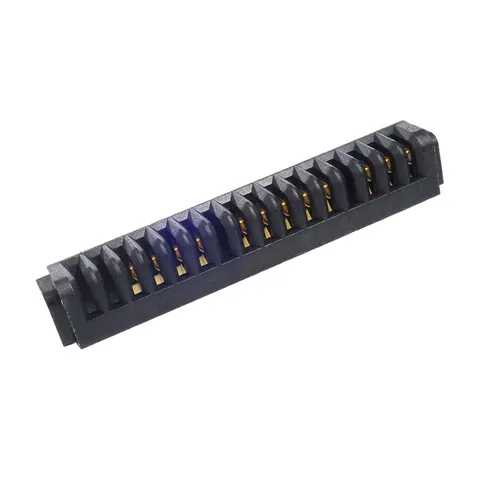
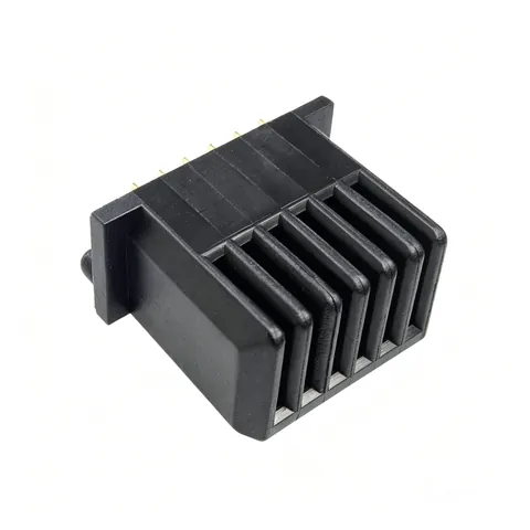
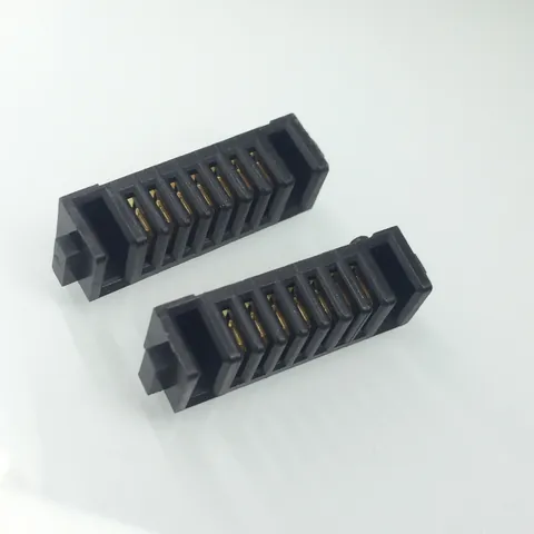
Synthesizing thermal laboratory rise curves and vibration qualification data from high-volume parts including the KS-BL-129 High-Current Blade Header, KS-BL-138 Heavy-Duty Receptacle, KS-BL-144, and KS-HC-11PIN Hybrid Connector, Kangsheng's engineering team details the contact thermodynamics, plating integrity, and pull-out retention benchmarks required for heavy-duty energy storage systems.
1. System Architecture: Why Blade Connectors Excel in Battery Interconnects
Across 500 W to 3000 W mobile and stationary power systems, powertrain designers generally evaluate four primary termination topologies: bolted terminal lugs, Anderson Powerpole connectors, circular multi-pin connectors, and modular blade connectors. The table below contrasts their engineering profiles:
| Evaluation Dimension | Blade Battery Connectors (e.g., KS-BL Series) | Anderson Connectors | Traditional Circular Pin Headers | Bolted Terminal Lugs |
|---|---|---|---|---|
| Continuous Current Rating | 20 A to 50 A continuous | 15 A to 45 A continuous | 3 A to 10 A | 50 A to 150 A |
| Mating Ergonomics | Smooth slide-in docking; polarized guide rails | Cable-to-cable manual plug | Prone to pin bending under load | Requires torque wrenches; non-swappable |
| Footprint / Profile | Compact board-mount profile; low insertion height | Bulky exterior footprint | Minimal space but inadequate current | Extremely large; severe vertical penalty |
| Micro-Vibration Immunity | Dual-beam wiping contact with high retention | Single contact leaf; prone to vibration drift | Single point; easily loses continuity | Subject to screw loosening under vibration |
| Automated Manufacturing | Fully compatible with SMT / Wave Soldering | Manual wire crimping only; high labor | Automated SMT | Strictly manual assembly |
| Primary Target Applications | Swappable E-bike battery packs, portable storage | Industrial lift trucks, external wire whips | Low-current auxiliary links | Commercial utility-scale energy storage racks |
In swappable pack infrastructures and compact modular enclosures, blade battery connectors have established complete industry dominance due to their sub-milliohm contact resistances, contact wiping redundancy, and generous blind-mating alignment tolerances.
2. Contact Physics: Joule Dissipation, Cross-Section Current Density, and Thermal Ceilings
2.1 Joule Heat Dissipation and Contact Resistance Thresholds
Thermal dissipation within heavy-duty terminals is governed strictly by Joule's Law: $P_{loss} = I^2 \cdot R_{contact} + I^2 \cdot R_{bulk}$
Where $R_{bulk}$ represents the volumetric bulk resistance of the copper alloy conductor, and $R_{contact}$ represents true physical interface resistance.
- At $I = 30\text{ A}$, maintaining a total loop contact resistance of $3\text{ m}\Omega$ results in a modest power dissipation of $P = 30^2 \times 0.003 = 2.7\text{ W}$;
- Should poor clamping force or surface tarnish allow contact resistance to climb to $15\text{ m}\Omega$, dissipation explodes to $13.5\text{ W}$! Within an unventilated sealed pack compartment, this heat accumulation will soften the plastic housing within 10 minutes, triggering catastrophic terminal melting.
Engineering Thermal Standards:
- In compliance with IEC 60512-5-2, after 2 hours of continuous 100% rated current loading, terminal temperature rise must hold $\Delta T \le 30\text{ K}$;
- Target current density should remain within $J \le 5\text{ A/mm}^2$. At 30 A continuous current, terminal effective cross-section must not fall below $6.0\text{ mm}^2$.
2.2 Terminal Alloy Selection and High-Temperature Stress Relaxation
Heavy continuous current generates significant conductor heat ($75^\circ\text{C}$ to $90^\circ\text{C}$ operating temperatures), imposing severe demands on female contact beam elasticity:
- Standard H65/H70 brass subjected to $80^\circ\text{C}$ ambient exposure for 500 hours loses over 35% of its normal contact force, dropping from $3.0\text{ N}$ down below $1.8\text{ N}$. This triggers a fatal thermal runaway cycle: inadequate contact force $\rightarrow$ escalating contact resistance $\rightarrow$ accelerated thermal rise $\rightarrow$ complete spring collapse;
- Kangsheng heavy-duty blade receptacles (such as the KS-BL-138) exclusively utilize C17200 Beryllium Copper or ultra-spring-temper C5210-EH Phosphor Bronze, maintaining high electrical conductivity and stress relaxation resistance up to $130^\circ\text{C}$. They retain more than 85% of their initial normal force after 1,000 hours of continuous thermal stress.
3. Plating Systems and Mechanical Retention Mechanics
3.1 Heavy Silver (Ag) vs Heavy Gold (Au) Plating
In automotive and high-cycle energy storage environments, plating selection governs electrical life and arc-erosion immunity:
- Heavy Silver Plating ($\ge 3\ \mu\text{m} \sim 5\ \mu\text{m}$ Ag over Ni):
Silver delivers the highest electrical and thermal conductivity of any metal, alongside high melting points that naturally resist minor hot-plug micro-arcing. Heavy-duty blade connectors prioritize bright hard silver plating paired with dual-beam wiping geometry to sustain $\le 3\text{ m}\Omega$ contact resistance even after 1,000 cycles.
- Selective Hard Gold Plating ($\ge 5\ \mu\text{''}$ Au over $1.27\ \mu\text{m}$ Ni):
Mandatory for hybrid connectors (such as the KS-HC-11PIN) carrying low-voltage BMS telemetry signals alongside high-current lines, safeguarding signals against atmospheric corrosion and salt spray.
3.2 Insertion, Retention, and Terminal Pull-Out Forces
Vehicle road shock imparts substantial axial and shear displacement forces onto battery interfaces:
- Insertion Force: To facilitate smooth battery pack swapping, individual blade insertion forces are tuned between $4\text{ N}$ and $8\text{ N}$;
- Retention / Pull-out Force: Once fully seated, terminal retention must hold $\ge 25\text{ N}$ (with multi-blade assemblies delivering total pull-out forces between $40\text{ N}$ and $80\text{ N}$), preventing micro-disconnections under 10G mechanical shock;
- Terminal Retention in Housing: Internal terminal retention barbs must resist push-out forces of $\ge 30\text{ N}$, preventing pin push-out failures when male blades engage the female housing.
4. Head-to-Head Kangsheng Heavy-Duty Blade Connector Specifications
| Parameter | KS-BL-129 (Compact Vertical Header) | KS-BL-138 (Heavy-Duty Receptacle) | KS-BL-144 (Right-Angle Wide-Pitch) | KS-HC-11M/F (Power & Signal Hybrid) |
|---|---|---|---|---|
| Rated Continuous Current | 25 A continuous / 35 A peak | 35 A continuous / 50 A peak | 30 A continuous / 45 A peak | Power: 25 A (4P) / Signal: 2 A (7P) |
| Terminal Architecture | Solid silver-plated blade (0.8 mm) | Symmetrical dual-beam clamping contact | Wide-pitch vertical creepage barrier | Staggered dual-pitch high-low profile |
| Initial Contact Resistance | $\le 5\text{ m}\Omega$ | $\le 3\text{ m}\Omega$ | $\le 4\text{ m}\Omega$ | Power: $\le 5\text{ m}\Omega$ / Signal: $\le 20\text{ m}\Omega$ |
| Operational Temp Rise ($\Delta T$) | $\le 25\text{ K}$ @ 20A continuous | $\le 22\text{ K}$ @ 30A continuous | $\le 28\text{ K}$ @ 25A continuous | $\le 26\text{ K}$ @ 20A continuous |
| Mechanical Endurance | $\ge 1,500$ cycles | $\ge 3,000$ cycles (hard silver) | $\ge 1,000$ cycles | $\ge 2,000$ cycles |
| Resin Flammability | UL94 V-0 (PA9T high-temp) | UL94 V-0 (glass-filled LCP) | UL94 V-0 (modified PA66) | UL94 V-0 (high-insulation PA9T) |
| Primary Applications | Solar generator output, e-scooter pack | Swappable battery dock, motor controller | Outdoor mobile storage, DC busbar | Smart LEV swappable pack with BMS |
5. Field Troubleshooting and Reliability Design Rules
- Failure Mode 1: Localized Plastic Discoloration and Housing Charring
- Root Cause: Incomplete mating depth (less than 2.0 mm engagement) or active hot-unplugging under heavy load causing destructive contact arcing.
- Engineering Solution: Integrate secondary positive latches into the battery chassis; incorporate soft-start FET controls or pre-charge relays on the controller board.
- Failure Mode 2: Solder Joint Cracking and PCB Pad Delamination
- Root Cause: Extreme bending moments exerted during manual pack insertion transferring directly into solder fillets without mechanical post relief.
- Engineering Solution: Choose connectors equipped with heavy-duty metal hold-down latches (solder nails) or molded screw-mounting flanges anchored directly to the metal chassis.
- Failure Mode 3: Intermittent Telemetry Loss Under Road Vibration
- Root Cause: Fretting wear from road shock causing micro-disconnections exceeding 1 microsecond.
- Engineering Solution: Specify dual-point redundant contact beams delivering a minimum normal contact force of $2.5\text{ N}$ per blade.
6. E-Bike & Storage Battery Connector Engineering FAQs
Q1: What creepage and clearance distances are required for 48V to 72V lithium battery platforms?
A: Under IEC 60664-1 standards for Pollution Degree 2 environments, 48V to 72V systems (with charging cut-offs up to 84V) require a minimum clearance of $\ge 1.5\text{ mm}$ and a minimum creepage distance of $\ge 2.5\text{ mm}$. Kangsheng KS-BL series connectors incorporate integrated dielectric partition barriers that expand effective creepage paths beyond $4.0\text{ mm}$, eliminating high-voltage arc-over risks.
Q2: Why should battery packs always feature female receptacles while host chassis use male blades?
A: Operator electrical safety. A disconnected lithium battery pack is an active, energized energy source. If exposed male blades protruded from the pack exterior, accidental contact with loose coins, keys, or wet debris would trigger dead-short arcing and fire. Female receptacles conceal energized metal contacts deep inside recessed housing cavities (compliant with IP2X finger-safe probes).
Q3: How do blade connectors compare with bolted copper busbars in portable energy storage?
A: Rigid bolted busbars are suitable only for permanent inter-cell connections inside battery enclosures. Blade connectors provide compliance against vibration, allow rapid modular assembly on production lines, and permit field replacement of battery packs without hand tools.
Q4: How does Kangsheng certify flammability compliance to UL94 V-0?
A: Kangsheng uses certified flame-retardant PA9T and LCP resin compounds tested in accordance with UL94 vertical burning protocols (flame self-extinguishes within 10 seconds without flaming drips). Materials also satisfy Glow Wire Flammability Index (GWFI $\ge 850^\circ\text{C}$) requirements for unattended appliance safety.
Q5: What custom design options does Kangsheng provide for extreme current loads (e.g., 80A continuous)?
A: Kangsheng operates vertically integrated tooling, high-speed stamping, and molding facilities. We provide custom terminal cross-sections and dual-blade configurations supported by in-house thermal finite element analysis (FEA). Engineering prototypes for temperature rise qualification are typically delivered within 15 business days.
CATALOGUE REFERENCES
Related products
YOUR NEXT DESIGN CHECK
Send us your drawing.
We’ll check pitch, height and compression against your assembly requirements.
Ask about this article