
ASSEMBLY & SELECTION GUIDE
Waterproof USB Type-C Connectors (IPX7/IPX8) for Industrial & Outdoor Equipment: Sealing Architecture and Selection Guide
In-depth engineering guide on waterproof USB Type-C connectors for rugged industrial and outdoor systems: dual-barrier sealing (O-ring compression 20%-30%, epoxy terminal potting), 6P/12P/24P pin tradeoffs, salt spray gold plating, and electrochemical mitigation.
In rugged industrial handhelds, outdoor surveying devices, light electric vehicle (LEV) auxiliary charge ports, portable medical monitors, and rugged consumer hardware, the USB Type-C interface has completely eclipsed legacy Micro-USB and proprietary barrel jacks. It delivers reversible mating ergonomics, rapid USB Power Delivery up to 100W (20V/5A) or 240W (EPR 48V/5A), and multi-gigabit data throughput across a unified form factor.
However, operating in outdoor downpours, salt spray humidity, mud, or transient immersion rapidly compromises non-sealed consumer connectors. Capillary action pulls liquids through microscopic pin interfaces, triggering pin-to-pin shorts, electrochemical migration, and irreversible motherboard destruction. Consequently, waterproof USB Type-C connectors meeting rigorous IPX7 (immersion at 1 meter for 30 minutes) and IPX8 (extended immersion at customer-specified depths) benchmarks represent a baseline engineering requirement for field-deployed hardware.
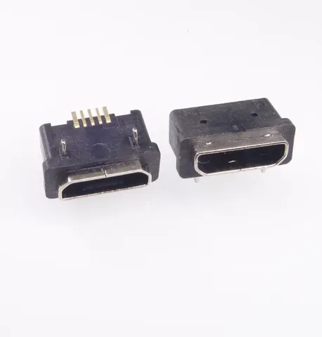
Drawing upon automated leak-testing data and precision tooling across Kangsheng's waterproof interconnect lineup—including the KS-USB-017 6-Pin Waterproof Charging Receptacle, KS-USB-018 12-Pin Waterproof Receptacle, KS-USB-025 High-Speed Type-C 3.1, KS-USB-006 Gasketed Receptacle, and KS-USB-094 IP67 Port—our engineering group analyzes dual-barrier hermetic architecture, pin-count trade-offs, and qualification protocols.
1. The Core Challenge: Dual-Barrier Sealing Architecture
A common misconception among junior engineers is that fitting an external rubber O-ring turns a standard Type-C into a waterproof connector. In reality, liquid penetration occurs along two distinct paths, necessitating a dual-barrier hermetic boundary:
1.1 Barrier 1: Panel-to-Shell Perimeter Sealing
- Leak Path: Liquids navigate the tolerance gap between the host chassis aperture and the connector's external stainless steel shell.
- Implementation: Radial or axial silicone O-rings or Liquid Silicone Rubber (LSR) multi-shot overmolding around the shell perimeter.
- Key Engineering Benchmarks:
- Interference Compression Ratio: The static compression ratio of the silicone gasket must remain strictly within ****. If compression drops below , structural tolerance stack-ups invite hydraulic blow-by; if compression exceeds , the polymer suffers irreversible compression set and rapid micro-cracking;
- Durometer Selection: We specify ** Shore A** liquid silicone to balance compliance against rough chassis walls with resilience against shear tearing during assembly;
- Aperture Lead-in Chamfer: The mating chassis cavity requires a smooth lead-in chamfer with internal surface finishes held to , preventing gasket pinching or cutting during blind insertion.
1.2 Barrier 2: Pin-to-Housing Internal Hermetic Sealing
- Leak Path: Moisture enters the receptacle mouth and wicks along the micro-crevices separating the stamped copper terminals from the injection-molded dielectric core (LCP/PA9T), penetrating straight onto the host PCB solder pads!
- Implementation:
- Dual-Cure UV & Thermoset Epoxy Potting: Automated dispensing heads apply high-viscosity, high-dielectric epoxy along the rear terminal exit channels. The compound undergoes UV pinning followed by thermal curing oven cycles to completely eliminate capillary voids;
- Precision Insert Molding: Metal terminals undergo chemical micro-etching to bond directly with thermoplastic resins. Kangsheng verifies 100% of production units via automated differential pressure decay testers (-50 kPa held for 15 seconds with zero bubble emission).
2. Pin Count and Data Speed vs. Sealing Trade-Offs: 6-Pin, 12-Pin, or 24-Pin?
In ruggedized field hardware, maximizing pin count is often an anti-pattern. Denser pin layouts decrease terminal pitch, constrain epoxy penetration channels, and increase vulnerability to electrolytic dendrite shorting under humid operating conditions. Engineers must align connector pin density with functional requirements:
| Evaluation Dimension | 6-Pin Waterproof Charging Port (e.g., KS-USB-017) | 12-Pin / 16-Pin Waterproof Port (e.g., KS-USB-018) | 24-Pin Full-Featured Type-C (e.g., KS-USB-025) |
|---|---|---|---|
| Pin Configuration | VBUS, GND, CC1, CC2 (Power & Fast-Charge Protocol only) | VBUS, GND, CC1, CC2, D+, D- (Top/Bottom symmetrical) | Complete USB 3.1 TX/RX pairs, SBU1/2, CC, VBUS, GND |
| Max Data Throughput | No Data (Power & Fast Charging Dedicated) | USB 2.0 (480 Mbps) | USB 3.1 Gen2 (10 Gbps) / USB4 (40 Gbps) |
| USB Power Delivery | Supports PD 2.0/3.0 (up to 20V/3A 60W or 20V/5A 100W) | Supports PD 3.0 (up to 100W) | Supports full 100W ~ 240W EPR profile |
| SMT Soldering Yield | Wide pin pitch, single-row pads; 99.9% SMT yield | Single-row or hybrid hybrid SMT; excellent yield | Fine 0.5mm dual-row SMT; stringent coplanarity () |
| Potting Channel Reliability | Broad epoxy channels; superior sealing margins | Robust flow geometry; mature mass-production stability | Dense terminal cluster requires micro-needle dispensing |
| Typical Target Applications | Industrial flashlights, e-bike charge ports, outdoor alarms | Rugged barcode scanners, survey instruments, field medical | High-speed industrial vision cameras, rugged laptops |
Selection Rule: If your hardware only requires charging or occasional low-speed field firmware upgrades (USB 2.0), specify 6-Pin or 12-Pin connectors (such as KS-USB-017 and KS-USB-018). Expanding pin pitch dramatically improves dielectric withstand margins, lowers fabrication cost, and eliminates over 80% of field water-ingress returns.
3. Electrical and Mechanical Durability Benchmarks
Rugged outdoor hardware must withstand severe mechanical and environmental abuse:
3.1 Salt Spray Immunity and Plating Integrity
Exposed maritime air and industrial sulfur degrade exterior shells and electrical contact leaves:
- Shell Metallurgy: Precision drawn SUS304 or SUS316 stainless steel shells protected by sub-micron nickel strike plus matte tin or electroless nickel over-plating, consistently achieving 48 to 96 hours of Neutral Salt Spray (ASTM B117) testing without red rust formation;
- Contact Plating: Contact beams feature high-spring phosphor bronze (C5191) with selective hard gold electroplating. For industrial field service, **specify to Au over nickel underplate**. Flash gold plating (< ) wears away within 500 mating cycles, exposing raw copper to ambient moisture and spiking interface resistance from into open circuits.
3.2 Mechanical Insertion Life and Retention Force
- Mating Durability: Tested in compliance with IEC 62680-1-3, maintaining intact spring compliance after 10,000 mating/unmating cycles;
- Insertion & Extraction Force: Initial insertion force is calibrated between **, with extraction retention held between **. Following 10,000 cycles, retention force must never drop below ;
- Wrenching Resistance: Chassis-mount variants feature lateral screw-down mounting tabs (ears) capable of absorbing torsional moments exceeding , shunting cable leverage stresses directly into the structural housing rather than the fragile PCB solder joints.
4. Kangsheng Core Waterproof & Type-C Connector Specifications
| Parameter | KS-USB-017 (6P Waterproof) | KS-USB-018 (12P Waterproof) | KS-USB-025 (3.1 Type-C) | KS-USB-006 (Gasketed USB) | KS-USB-094 (IP67 Micro-USB) |
|---|---|---|---|---|---|
| Form Factor | USB Type-C (6-Pin) | USB Type-C (12-Pin) | USB Type-C 3.1 (24-Pin) | USB Type-A (Short-body Gasket) | Micro-USB (5-Pin Waterproof) |
| Ingress Rating | IPX7 / IPX8 Verified | IPX7 / IPX8 Verified | Dust-resistant / Standard | IPX7 Face-seal | IP67 (Through-hole shell + SMT) |
| Rated Current | 3.0A (5.0A Custom available) | 3.0A ~ 5.0A (PD 100W) | 5.0A Full PD Profile | 1.5A ~ 2.0A | 1.8A Standard |
| Sealing Architecture | Silicone O-Ring + Rear Epoxy | Silicone O-Ring + Rear Epoxy | Mechanical Shield | Rubber Gasket Face | Pin Potting + Front Face Seal |
| Contact Resistance | |||||
| Insulation Resistance (Submerged) | |||||
| Mounting Profile | Top-Mount / Mid-Mount SMT | Mid-Mount (Drop-in) / Top | Standard SMT | DIP Through-Hole | 4-post Through-Hole anchor |
| Target Application | Outdoor flashlights, e-bike chargers | Survey instruments, rugged tablets | Vision capture, rugged PCs | Industrial enclosure USB | Legacy field instrument spares |
5. Field Failure Troubleshooting and DFM Guidelines
- Failure Mode 1: Gasket brittleness, shrinkage, or thermal deformation following reflow
- Root Cause: Assembly personnel pre-installed the silicone O-ring onto the connector prior to SMT wave/reflow soldering. Peak lead-free reflow temperatures () destroy common silicone elastomeric bonds.
- Correct DFM Flow: Implement post-reflow gasket assembly (fit the O-ring onto the connector neck during final enclosure assembly). If automated reflow requires pre-fitted seals, mandate fluorosilicone compounds rated for exposure.
- Failure Mode 2: Gasket shear tearing upon enclosure insertion
- Root Cause: Unchamfered enclosure openings with sharp machining burrs cut the silicone ring during blind slide-in assembly.
- Corrective Measure: Mandate a smooth opening lead-in ( or chamfer) and apply micro-doses of NSF-certified silicone lubricant.
- Failure Mode 3: Rapid VBUS pin blackening and electrolytic erosion under energized immersion
- Root Cause: Even when internal housing sealing prevents water from penetrating into the PCBA, water pooling inside the exterior receptacle plug while VBUS remains energized at 20V initiates vigorous electrochemical electrolysis.
- Circuit Mitigation: Implement CC-pin-controlled load switches. Ensure VBUS remains completely unpowered until a valid cable termination handshake is completed; immediately de-energize upon cable disconnect.
6. Waterproof Type-C Engineering FAQs
Q1: What is the formal difference between IPX7 and IPX8 ratings?
A: Under IEC 60529, IPX7 requires complete water exclusion when immersed at 1 meter for 30 minutes. IPX8 is customized between manufacturer and OEM, typically demanding immersion depths of 2m, 5m, or 10m for durations spanning 24 hours to 7 days. Kangsheng tests 100% of production waterproof connectors using dry pneumatic vacuum decay testers (-50 kPa held for 15s) to eliminate porous defects.
Q2: Why are mid-mount (drop-in) waterproof Type-C receptacles preferred in slim designs?
A: Mid-mount connectors position the connector center line coplanar with the PCB edge cutout, reducing vertical Z-axis profile height by 1.0mm to 1.5mm. Furthermore, mid-mount wings grip the PCB from both sides, providing superior shear resistance against levering forces.
Q3: Does rainwater accumulating in the exterior receptacle mouth damage unpowered equipment?
A: No. The internal potting seal prevents liquid from reaching the interior circuit. If rainwater enters the open socket while unpowered, simply shake or blow out the pooled moisture and let the socket air-dry before inserting a powered charging cable.
Q4: Can Kangsheng waterproof Type-C connectors survive medical autoclaves or chemical disinfectants?
A: Medical applications require specialized polymer and seal selection. Kangsheng offers custom configurations with fluorocarbon (FKM) gaskets and chemical-resistant shell coatings that resist degradation from 75% isopropyl alcohol, sodium hypochlorite, and routine wipe-down sterilization.
Q5: Can Kangsheng engineer custom flange plates and chassis mounting ears?
A: Yes. Kangsheng maintains in-house CNC and stamping toolrooms. We fabricate customized stainless steel flanges, polarizing alignment pins, and custom O-ring grooves to match your proprietary chassis castings, delivering evaluation samples in as few as 10 business days.
CATALOGUE REFERENCES
Related products
YOUR NEXT DESIGN CHECK
Send us your drawing.
We’ll check pitch, height and compression against your assembly requirements.
Ask about this article