
ASSEMBLY & SELECTION GUIDE
Push Button & Key Switch Selection: Latching vs Momentary Mechanics, Contact Bounce Suppression, and High-Cycle Durability
Comprehensive engineering guide on push button and key switches: heart-shaped cam latching vs momentary kinematics, dual-cantilever contact bounce suppression (≤2.0ms), contact wiping action, DC inrush arc protection, and tactile stroke profiles.
Across industrial human-machine interfaces (HMI), professional stage audio mixers, security consoles, automotive dashboard clusters, and heavy-duty commercial appliances, Push Button Switches (e.g., standard 5.8×5.8mm, 7×7mm, and 10×10mm footprints) and Key Switches serve as the frontline physical interactive interface directly evaluating tactile quality and system reliability.
While frequently dismissed as simple commodity mechanisms that just "toggle power on and off," field service data reveals three chronic mechanical and electrical failure modes:
- Heart-Shaped Cam Latching Jam & Delatching Failure: Self-locking (Latching / Alternate-Action) switches rely on an internal sub-millimeter guide wire traveling along an enclosed heart-shaped cam track. When users push actuators off-axis or thermal swings alter housing tolerances, the guide pin binds in dead-corners, leaving the button permanently jammed down;
- Excessive Contact Bounce Triggering False Microcontroller Interrupts: Mechanical contact closure involves micro-scale elastic rebounds. If contact bounce persists beyond , high-speed microcontroller (MCU) external interrupt routines register multiple false keystrokes during a single actuation;
- DC Inrush Arc Welding & Contact Pitting: In DC circuits (such as 12V/24V industrial buses), direct current lacks the natural periodic zero-crossing extinction of AC power. Sustained plasma arcing during contact opening erodes metal surfaces, culminating in destructive contact welding.
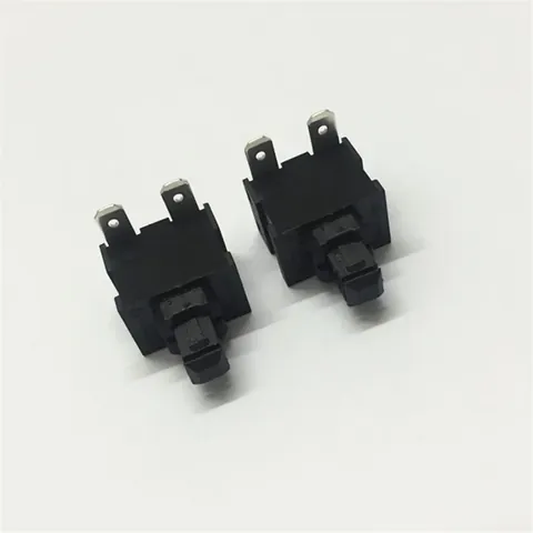
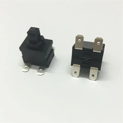
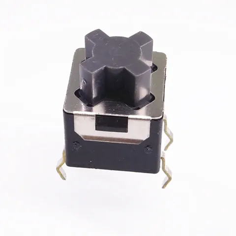
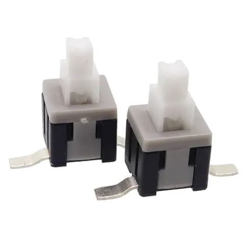
Synthesizing mechanical endurance cycles and thermal rise qualification across Kangsheng's high-reliability push button and key switch lines—including the KS-按键-001 2-Pin High-Current Switch, KS-按键-002 4-Pin Latching/Momentary Switch, KS-按键-003 10×10mm Cross-Actuator Switch, KS-按键-007 5.8mm SMT Tall-Button Switch, and KS-按键-010 5.8mm SMT Push Switch—our engineering group analyzes cam kinematics, contact wipe physics, and robust design practices.
1. Mechanism Kinematics: Self-Locking (Latching) vs. Momentary Mechanical Architectures
Push button switches divide fundamentally into two kinematic families:
1.1 Latching / Self-Locking Architecture (Alternate Action)
- Core Internal Mechanism: The internal slider incorporates a closed, single-direction cyclic heart-shaped cam groove (Heart-Shaped Track) engaged with a precision tempered piano-wire guide pin.
- Two-Stroke Kinematic Cycle:
- First Stroke (Depression & Lock): Downward slider displacement drives the guide pin over an inclined ramp into the heart-shaped notch, locking the button in its lowered state (Lock Position) with contacts continuously closed;
- Second Stroke (Release & Reset): A slight secondary over-travel stroke unseats the guide pin from the notch, steering it along the exit channel. A heavy-duty internal helical spring drives the slider back to its elevated Free Position, cleanly opening the circuit.
- Failure Boundary: The ramp drop within the heart-shaped track measures only . If off-axis actuation angles exceed , the guide pin twists laterally and binds against sidewalls. Kangsheng incorporates four corner-guide stabilizing ribs around the plunger body to eliminate off-axis jamming.
1.2 Momentary / Non-Locking Architecture
- Mechanical Principle: Eliminates the heart-shaped cam and guide pin, retaining only the primary helical return spring and movable contact bridge.
- Kinematic Profile: Circuits engage during active depression and open instantaneously within **** once the operator's finger releases.
- Endurance Advantage: Free from cam track frictional wear, momentary switches routinely achieve mechanical lifespans of 100,000 to 300,000 cycles, far exceeding latching counterparts (typically 10,000 to 50,000 cycles).
2. Contact Physics: Contact Wiping Action, Bounce Suppression, and Plating Stacks
Push button switches feature sliding movable contact bridges whose dynamic mechanics govern electrical reliability:
2.1 Contact Bounce Time Suppression and Hardware Debouncing
As the movable contact slams against stationary contact leaves, kinetic impact induces micro-scale bounces:
- Unoptimized commodity switches exhibit bounce times exceeding ****;
- Kangsheng Dual-Cantilever Balanced Leaf Architecture: Utilizes precision beryllium copper or phosphor bronze leaves stamped into dual-symmetrical curved runners. As they engage, dynamic kinetic energy is dissipated between opposed beams, suppressing bounce durations strictly below ****;
- Circuit Design Mandate: Integrate an RC low-pass filter at the MCU GPIO input (, time constant ) paired with a firmware debouncing delay to guarantee noise-free state acquisition.
2.2 Contact Wiping Action
Unlike tactile dome switches that meet perpendicularly, Kangsheng push button movable contact bridges execute an axial sliding stroke of **** across stationary terminal pads:
- This mechanical wiping action physically cuts through and scrubs away ambient sulfide films, dust particles, and thin organic oils during every actuation;
- Paired with heavy silver plating ( Ag) or hard gold over nickel ( Au over Ni), initial bulk contact resistance remains stable at ****, shifting less than over tens of thousands of cycles.
3. Tactile Ergonomics: Operating Force, Total Travel, and Lock Depth
For broadcast audio mixers and industrial consoles where tactile feedback is critical, mechanical stroke profiles define user satisfaction:
- Total Travel: Typically calibrated between ****, providing distinct physical travel feedback;
- Lock Travel (Latching Variants): In the locked state, the actuator remains depressed by of total travel (approximately below resting height), allowing operators to verify channel status instantly by visual inspection or finger touch;
- Operating Force (OF):
- Consumer / Audio Console Grade: (silky actuation for audio faders and consoles);
- Industrial Interlock Grade: (firm resistance preventing accidental activation).
4. Kangsheng Core Push Button Switch Specifications
| Parameter | KS-按键-001 (High-Current 2P) | KS-按键-002 (4P High-Current) | KS-按键-003 (10×10mm Cross) | KS-按键-007 (5.8mm SMT Tall) | KS-按键-010 (5.8mm SMT Flat) |
|---|---|---|---|---|---|
| Footprint Profile | Compact High-Current Button | Standard Square Power Button | 10×10mm Industrial Button | 5.8×5.8mm Subminiature SMT | 5.8×5.8mm Subminiature SMT |
| Kinematic Style | Latching / Momentary Option | Latching / Momentary Option | Heavy-Duty Latching Standard | Latching / Momentary Option | Momentary Self-Reset |
| Electrical Rating | 1A 30VDC / 0.5A 250VAC | 1A 30VDC / 0.5A 250VAC | 2A 30VDC / 1A 250VAC | 0.5A 30VDC / 0.3A 50VDC | 0.5A 30VDC Logic Level |
| Actuator Style | Cylindrical Tall Plunger | Square Anti-Rotation Plunger | Standard Cross-Shaft (Keycap) | Elevated Round Actuator | Low-Profile Flush Actuator |
| Mounting Style | Through-Hole DIP (2-Pin) | DIP Straight / Bent (4-Pin) | Through-Hole DIP Stiffeners | Surface-Mount SMT with Post | Surface-Mount SMT Flush |
| Contact Resistance | Ultra-low | ||||
| Mechanical Life | operations | operations | extended cycles | operations | operations |
| Target Application | Main instrument power toggles | HMI channel selectors, mixers | Industrial automation panels | Security sensor resets, radios | Smart thermostat side-buttons |
5. Field Failure Troubleshooting and DFM Guidelines
- Failure Mode 1: Button jams solid and cannot be depressed following SMT reflow
- Root Cause: Flux volatiles outgassed aggressively during reflow soldering, entering housing crevices and condensing inside the heart-shaped track. Cooling flux cured into a sticky lacquer that bound the delicate guide wire.
- Corrective Measure: Specify sealed base variants featuring epoxy-sealed terminal posts; apply protective Kapton tape over bottom seams before soldering; optimize reflow thermal ramp rates to eliminate flux spitting.
- Failure Mode 2: External decorative keycaps bind and rub against the front panel bezel
- Root Cause: Tolerance stack-ups between the PCB, switch centerline, and front panel bezel aperture exceeded mechanical clearances, causing severe lateral binding.
- Corrective Measure: Maintain at least ** radial clearance** between the decorative keycap and bezel openings; select switches featuring integrated guide channels (e.g., KS-按键-003).
- Failure Mode 3: Contacts weld shut after switching 24V relay coils for two weeks
- Root Cause: Unsnubbed inductive energy in the DC coil discharged across opening switch contacts, igniting continuous plasma arcs that vaporized silver plating.
- Corrective Measure: Position a flyback freewheeling diode (e.g., 1N4007) or TVS diode directly across the inductive coil to clamp back-EMF spikes within safe boundaries.
6. Push Button Switch Engineering FAQs
Q1: How do engineers visually verify Latching vs. Momentary models on the bench?
A: Under unpowered manual depression: if the plunger sinks with a crisp click and remains locked at a lower height, needing a second press to rebound, it is Latching. If releasing your finger instantly returns the plunger to full height, it is Momentary. Kangsheng part packaging explicitly codes "L" (Locking) and "M" (Momentary).
Q2: Why do high-current push button switches typically feature 4 pins rather than 2?
A: 4-pin configurations utilize dual parallel contact bridges to halve current density or provide Double-Pole Single-Throw (DPST) isolation of both hot and neutral lines. Furthermore, a 4-pin quadrilateral solder footprint delivers superior mechanical anchoring against aggressive user force, preventing PCB pad peel-off.
Q3: How does Kangsheng guarantee uniform tactile feel across multi-channel audio panels?
A: Tactile consistency depends on helical spring rate tolerances and slider tooling precision. Kangsheng assembles switches on automated lines where 100% of springs undergo dynamic force grading. Operating forces are held strictly within ****, ensuring that 16 or 32 adjacent mixer channels exhibit identical resistance and lock depth.
Q4: What temperature and flammability ratings do Kangsheng push button switches fulfill?
A: Housings are injection molded from 30% glass-filled heat-stabilized PA66/PA9T fulfilling UL94 V-0 flame ratings and passing Glow Wire Flammability Index (GWFI) tests at . They operate continuously across environments.
Q5: Does Kangsheng supply customized actuator heights and decorative keycaps?
A: Yes. In addition to standard cylindrical, square, and cross shafts, Kangsheng provides custom-molded ABS/PC keycaps in custom colors, transparent light-pipe windows, and custom laser-etched ISO legends.
CATALOGUE REFERENCES
Related products
YOUR NEXT DESIGN CHECK
Send us your drawing.
We’ll check pitch, height and compression against your assembly requirements.
Ask about this article