
ASSEMBLY & SELECTION GUIDE
Precision Slide Switch Contact Resistance and Life Degradation: Low-Frequency Micro-Motion and Environmental Oxidation on Signal Continuity
In-depth engineering analysis of contact resistance degradation in precision miniature slide switches (MSK/SS series): Holm contact mechanics, wiping action, silver sulfidation, fretting wear, and SMT reflow guidelines.
Precision slide switches (e.g., miniature MSK, SS, SK, and SSSS series) are ubiquitous across portable instruments, audio equipment, industrial handheld terminals, and consumer electronics power/mode selector circuits. Hardware designers routinely focus on package dimensions, mounting footprint (SMT vs Through-hole DIP), and switch configurations (1P2T, 2P3T), yet frequently overlook subtle contact resistance degradation driven by low-frequency micro-motion, thermal stress, and atmospheric oxidation.
In low-voltage sensor routing (such as audio path selection, ADC reference voltage switching, and microcontroller GPIO configuration) as well as battery-powered rails, an abrupt shift in contact resistance from tens of milliohms ($\le 50\text{ m}\Omega$) to several ohms can trigger voltage telemetry errors, logic level misreads, or unexpected system resets.
Drawing upon mechanical endurance testing data and field failure analysis from high-volume parts like the KS-SS-042 Miniature Slide Switch and KS-SS-006 Standard Side-Actuated Slide Switch, Kangsheng's engineering team provides an exhaustive examination of slide switch contact physics, wiping shear mechanisms, silver tarnishing, and reflow soldering thermal rules.
1. Contact Physics: Sliding Shear Friction and Holm Contact Theory
Unlike the vertical compression contact mechanism in tactile pushbuttons, a slide switch establishes circuit continuity through horizontal shear motion: the sliding actuator drives an internal moving contact clip across stationary terminal contacts.
Under Holm electrical contact theory, metallic surfaces are microscopically rough with micro-asperities. Real electrical contact occurs solely across tiny microscopic contact interfaces termed "conducting spots (A-spots)". Total contact resistance $R_{contact}$ comprises two distinct terms:
- Constriction Resistance ($R_c$): Additional electrical resistance induced as current streamlines contract through minute conducting spots.
$R_c = \frac{\rho}{2 \cdot \sum a_i}$ Where $\rho$ is material resistivity and $a_i$ represents the radius of each discrete A-spot. Higher normal contact force ($F_n$) forces asperities into plastic deformation, enlarging total conducting area and driving down constriction resistance.
- Film Resistance ($R_f$): Microscopic oxide, sulfide, or organic contaminant films naturally form on exposed metals. Current must overcome these layers through mechanical wiping rupture or voltage breakdown (fritting).
The primary mechanical virtue of slide switches is their wiping action. As the actuator toggles, the contact clip slides across the terminal surface over a distance of $0.5\text{ mm}$ to $1.5\text{ mm}$. This dynamic shear friction cuts through light surface oxidation and dust, exposing virgin metallic base material and stabilizing initial contact resistance well below $30\text{ m}\Omega$.
2. Core Drivers of Contact Resistance Degradation
During extended operating lifetimes, why do contact resistances drift upward? Real-world failure analyses identify three dominant failure mechanisms:
2.1 Atmospheric Silver Sulfidation and Oxidation
Most miniature slide switches employ silver-plated copper alloy contacts and terminals due to silver's outstanding electrical conductivity and galling resistance. However, in non-hermetic enclosures:
- Trace atmospheric sulfur dioxide ($SO_2$) and hydrogen sulfide ($H_2S$) react spontaneously with silver to form silver sulfide ($Ag_2S$) tarnish films. Silver sulfide is a semiconductor compound with resistivity thousands of times higher than pure silver.
- If the switch rests in a static state without actuation for months under "dry circuit" conditions (signal current $\le 1\text{ mA}$, voltage $\le 20\text{ mV}$), the absence of mechanical wiping or electric breakdown causes circuit resistance to drift into the multi-ohm range.
2.2 Fretting Wear and Low-Frequency Vibration
When hardware operates in vibrating environments (e.g., portable motor tools, power scrubbers, or automotive telematics):
- Vibration and thermal cycling produce cyclic micro-displacements ($1\ \mu\text{m}$ to $50\ \mu\text{m}$) across closed contact interfaces;
- This fretting motion continually pulverizes surface oxides into fine, non-conductive metallic debris. Accumulated fretting debris insulates the contact interface, causing random resistance spikes and intermittent opens.
2.3 Spring Stress Relaxation Under Thermal Exposure
Miniature slide switch moving clips are engineered with nominal normal forces between $0.8\text{ N}$ and $1.8\text{ N}$. When subjected to SMT reflow heat profiles (peak $260^\circ\text{C}$) or prolonged ambient thermal loading ($\ge 70^\circ\text{C}$), inferior bronze alloys suffer irreversible lattice slippage and stress relaxation. A 20% to 35% decline in normal force shrinks the effective A-spot area, accelerating contact failure.
3. Head-to-Head Kangsheng Slide Switch Specifications
The table below contrasts key engineering parameters across representative Kangsheng slide switches:
| Parameter | KS-SS-042 (Miniature SMT) | KS-SS-006 (Industrial Side-Slide) | KS-SS-012 (Long-Life Through-Hole) | KS-SS-020 (High-Retention Post SMT) |
|---|---|---|---|---|
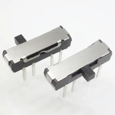
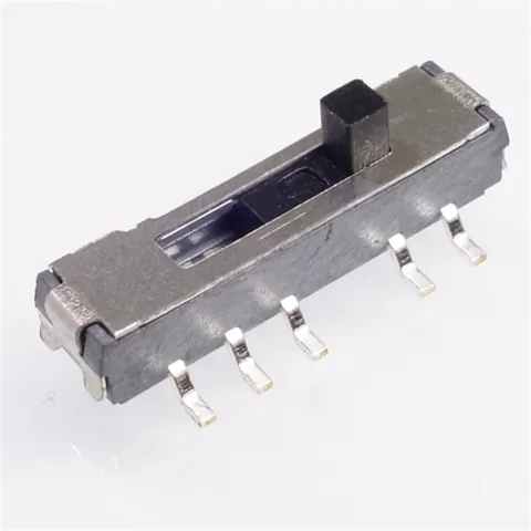
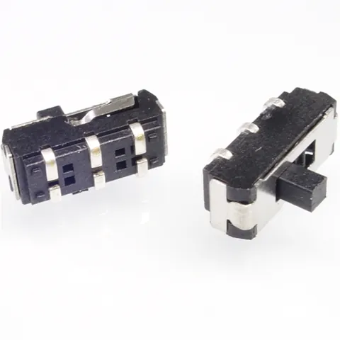
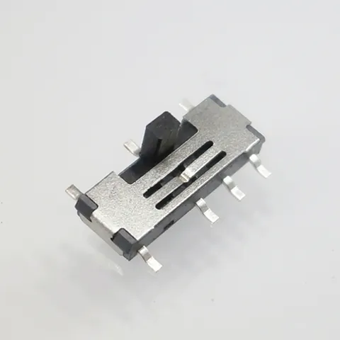
| Mounting & Form Factor | Ultra-miniature SMT · Horizontal actuator | Standard DIP / SMT side-toggle | Vertical through-hole DIP | Surface-mount with side solder tabs |
| Circuit Configuration | 2P3T / 1P2T precision micro-signal | 1P2T standard line switch | 2P2T dual synchronous switch | 1P2T ruggedized design |
| Electrical Rating | DC 12 V, 0.1 A | DC 24 V, 0.3 A | DC 50 V, 0.5 A | DC 12 V, 0.5 A |
| Initial Contact Resistance | $\le 30\text{ m}\Omega$ | $\le 50\text{ m}\Omega$ | $\le 30\text{ m}\Omega$ | $\le 40\text{ m}\Omega$ |
| Endurance Contact Resistance | $\le 100\text{ m}\Omega$ (10,000 cycles) | $\le 150\text{ m}\Omega$ (10,000 cycles) | $\le 100\text{ m}\Omega$ (20,000 cycles) | $\le 120\text{ m}\Omega$ (30,000 cycles) |
| Operating Force | $180 \pm 50\text{ gf}$ | $250 \pm 80\text{ gf}$ | $200 \pm 50\text{ gf}$ | $350 \pm 100\text{ gf}$ |
| Housing Resin Material | High-temp PA9T / LCP ($260^\circ\text{C}$) | High-insulation PA66 | Flame-retardant PBT | Glass-filled PA9T |
| Primary Applications | Wearables, TWS cases, precision instrumentation | Industrial power switches, test tools | Control board isolation, medical handhelds | Automotive aux configs, ruggedized devices |
4. Engineering Design & Selection Checklist
To safeguard electrical continuity across equipment operational lifecycles, hardware designers should observe five design rules:
- Match Contact Plating to Circuit Electrical Energy:
- For power or digital lines carrying $\ge 50\text{ mA}$ at $\ge 5\text{ V}$, heavy silver plating ($\ge 2\ \mu\text{m}$ Ag) delivers outstanding conductivity and cost efficiency; minor micro-arcing and mechanical wipe maintain clean contact asperities.
- For sub-milliamp sensor inputs (thermocouples, high-impedance audio, low-power MCU sleep-wake lines), specify selective gold plating ($\ge 3\ \mu\text{''}$ Au over Ni) to eliminate silver tarnish formation entirely.
- Audit SMT Reflow Thermal Rating:
Miniature SMT slide switches feature small resin volumes fully exposed to reflow oven heat. Standard PBT resins distort above $230^\circ\text{C}$, pinching internal sliding guides and freezing toggle action. Demand high-temperature engineering thermoplastics (PA9T / LCP with deflection thresholds $\ge 260^\circ\text{C}$), ensuring internal moving clips preserve designed normal forces post-reflow.
- Allow Mechanical Actuator Clearances:
Enclosure knobs and switch levers must incorporate nominal clearances ($0.15\text{ mm}$ to $0.25\text{ mm}$ per side). Never allow external enclosure fascias to exert downward Z-axis force on the toggle lever, which cocks the internal slider and accelerates mechanical wear by 3x.
- Prevent Solder Flux Intrusion:
During wave soldering, capillary action can draw flux liquid up through terminal bases into the internal cavity. Dried rosin and organic acids insulate contacts, causing complete open-circuit failures. Select SMT switches with insert-molded, epoxy-sealed terminal bases (such as KS-SS-042), and hold hand-soldering iron dwell times strictly below $350^\circ\text{C} \le 3\text{ s}$.
- Periodic Self-Cleaning Guidelines:
For equipment where switches remain in static positions for months, include a simple self-cleaning note in maintenance manuals: toggling the switch 3 to 5 times periodically mechanically sweeps away accumulated tarnish and restores milliohm-level contact resistance.
5. Failure Symptoms and Root-Cause Matrix
| Observable Symptom | Microscopic Root Cause | Bench Verification Method | Definitive Countermeasure |
|---|---|---|---|
| Intermittent logic errors / dropouts | Fretting wear accumulates insulating black debris | Toggling actuator rapidly 10x temporarily recovers impedance | Upgrade to dual-wiping contact clips or selective gold plating |
| Actuator sticks / freezes post-reflow | Plastic housing warps from heat/moisture exposure | Disassemble and inspect guide track under optical microscope | Specify PA9T / LCP resin and follow factory MSL dry-pack baking |
| Tactile feel loosens; resistance erratic under vibration | Terminal spring stress relaxation; reduced normal force | Measure actuation force with gauge (>40% force drop) | Specify high-yield phosphor bronze contact springs |
| Switch permanently open post-assembly | Solder flux wicks along pins and coats contacts | Inspect opened terminal face under magnification for flux residue | Use sealed insert-molded bases or zero-clean solder paste |
6. Precision Slide Switch Engineering FAQs
Q1: Can a slide switch rated at DC 12V 0.1A be used for 3.3V 10uA low-power MCU GPIO sensing?
A: Yes, but plating selection is paramount. At 3.3V 10uA, the circuit operates in a classic "dry circuit" condition where voltage cannot break down micro-thin surface oxide films. Standard silver plating left dormant will accumulate silver sulfide tarnish, driving resistance into the kilohm range and corrupting logic readings. For low-current micro-signal applications, specify custom gold-plated contacts (such as gold-flashed KS-SS-042) to guarantee uncompromised signal continuity.
Q2: What is the difference between 1P2T, 2P2T, and 2P3T slide switches?
A: "P" denotes Poles (the number of independent circuits switched concurrently), and "T" denotes Throws (the number of switchable output positions per pole).
- 1P2T (Single-Pole Double-Throw, typically 3 pins): 1 common pin switching between output A and output B;
- 2P2T (Double-Pole Double-Throw, typically 6 pins): Two electrically isolated 1P2T switches actuated by a single lever, ideal for dual-rail power or balanced signal switching;
- 2P3T (Double-Pole Triple-Throw, typically 8 pins): Two independent circuits each addressing three discrete positions (e.g., Off / Mode 1 / Mode 2).
Q3: Why is slide switch mechanical endurance typically rated at 10,000 cycles?
A: The slide switch mechanism relies on continuous sliding friction between the moving contact clip and fixed terminals, incurring micro-wear with every cycle. Standard miniature slide switches are optimized for 10,000 to 30,000 cycles under rated electrical load. They are engineered for configuration, mode selection, and power gating rather than high-frequency user-facing buttons (for high-cycle inputs, select tactile switches or micro switches).
Q4: How do designers ensure SMT slide switches withstand manual shear forces without pad tearing?
A: When users slide the toggle lever, lateral shear forces reach 2 N to 5 N. Soldering only signal pins creates high stress concentrations that can rip copper pads off the PCB. Designers must select switches equipped with robust metal retention tabs (solder lugs) on both chassis sides (such as KS-SS-006 SMT), tie these tabs to expansive ground copper pours, and stitch multiple thermal vias to deliver exceptional peel resistance.
Q5: What critical dimensions do European engineers verify when requesting 3D STEP models?
A: When European hardware engineers (in medical, test instrumentation, or smart IoT sectors) request 3D CAD models, they evaluate three primary interfaces:
- Enclosure Aperture Clearances: The switch lever cross-section and total actuator travel (stroke) relative to front-panel slots, preventing binding or aesthetic gaps;
- Automated Pick & Place Area: Ensuring adequate flat vacuum nozzle landing space or removable Kapton high-temp tape on top;
- Pin Coplanarity & Component Keep-Out Zones: Verifying pin footprints and post holes against nearby surface-mount passives. Kangsheng provides certified 3D STEP models and 2D engineering PDFs for its entire slide switch line upon request.
CATALOGUE REFERENCES
Related products
YOUR NEXT DESIGN CHECK
Send us your drawing.
We’ll check pitch, height and compression against your assembly requirements.
Ask about this article