
ASSEMBLY & SELECTION GUIDE
DC Power Jack and 3.5mm Audio Jack Selection: Center Pin Tolerances, Normally-Closed Switch Oxidation, and Mating Durability
Comprehensive engineering guide on DC barrel jacks and 3.5mm phone jacks: 5.5x2.1mm vs 5.5x2.5mm center pin tolerance matching, normally-closed (NC) shunt switch contact oxidation and anti-tarnish dimple design, and metal shield retention mechanics.
Across industrial control cabinets, networking gateways, professional audio gear, portable medical monitors, and battery-powered consumer hardware, cylindrical DC Barrel Jacks (such as industry-standard DC-005 and DC-002 lines) and 3.5mm Phone Jacks (such as PJ-320 and PJ-123 lines) are among the most heavily mated—yet most frequently overlooked—interconnects.
While often treated as interchangeable commodity plastic housings, real-world deployment reveals two severe engineering pitfalls:
- Center Pin Dimensional Incompatibility: Standard 5.5mm outer diameter DC plugs come in two visually indistinguishable inner diameter formats: 2.1mm and 2.5mm. Inserting a 2.5mm ID plug into a 2.1mm pin receptacle yields inadequate contact normal force, inducing sustained micro-arcing, dramatic interface resistance spikes, and severe plastic housing melting;
- Normally-Closed (NC) Shunt Switch Oxidation: Pin 3 in a DC jack (battery-to-adapter changeover shunt) and internal leaf switches in 3.5mm audio jacks remain exposed to ambient moisture and airborne pollutants. Because normally-closed contacts lack the mechanical wiping action of active mating, stagnant interfaces form non-conductive oxide films, triggering classic failures where hardware fails to switch back to internal battery power upon unplugging.
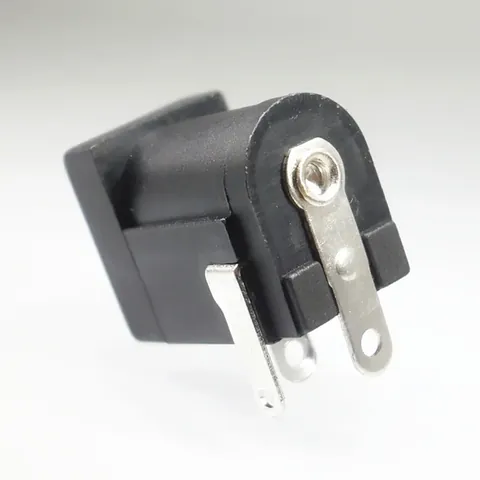
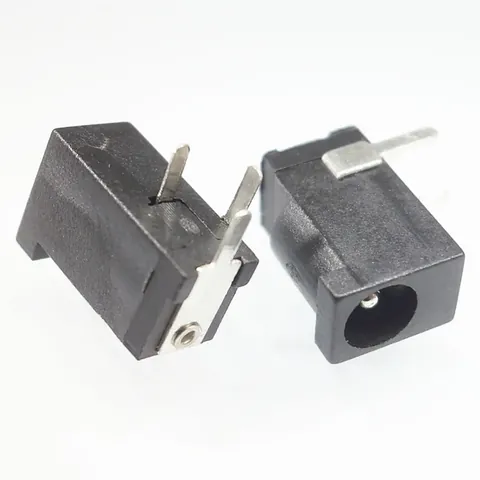
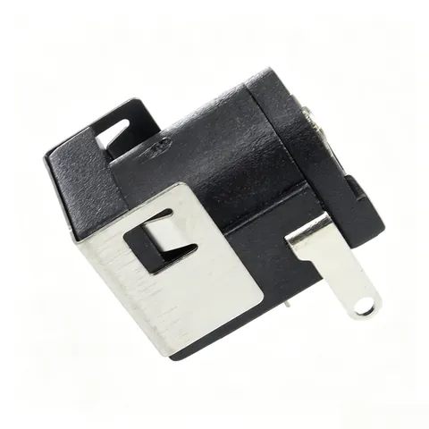
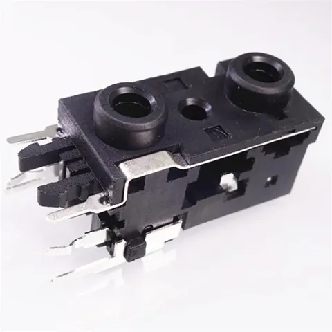
Synthesizing mechanical endurance cycles and thermal rise qualification across Kangsheng's high-reliability power and audio interconnects—including the KS-DC-008 Standard DC-005 Jack, KS-DC-003 Compact DC-002 Jack, KS-DC-013 Metal-Shielded Rugged Jack, KS-PJ-001 3.5mm Audio Jack, and KS-PJ-004 Dual-Stack Audio Jack—our engineering group analyzes pin tolerances, shunt switch degradation, and durable selection guidelines.
1. Mating Mechanics: Pin Diameters, Normal Force, and Joule Heating
A DC barrel interface utilizes an outer cantilever spring to grip the plug exterior (typically Ground) while a solid brass center pin engages the plug's inner cylindrical cavity (typically Positive).
1.1 The 5.5×2.1mm vs 5.5×2.5mm Dilemma
- 2.1mm Format (e.g., KS-DC-008): Center pin diameter is calibrated to , delivering of retention against 2.1mm tuning-fork plugs;
- 2.5mm Format: Center pin diameter is calibrated to , engineered to handle higher continuous currents (5A to 10A);
- Mismatch Hazards: Mating a 2.5mm plug onto a 2.1mm pin leaves a 0.4mm physical air gap, reducing contact to a single tenuous point. Under a typical 12V/3A (36W) workload, contact resistance escalates from into multiple ohms. Dissipating over 10 watts across a tiny interface melts thermoplastic housings within minutes.
1.2 Spring Leaf Geometries: Single Cantilever vs High-Elasticity Phosphor Bronze
- Standard Flat Cantilevers: Budget stamped leaves suffer plastic deformation after 1,000 cycles, losing more than 50% of initial normal force;
- Kangsheng Curved Phosphor Bronze Leaves (C5210-EH): Engineered dual-radius curvatures preserve normal clamping force across 5,000 to 10,000 mating cycles, keeping contact resistance strictly under .
2. The Hidden Failure Point: NC Shunt Switch Degradation
In a standard DC jack, Pin 1 (Center Pin), Pin 2 (Primary Ground Leaf), and Pin 3 (Normally-Closed Shunt Leaf) create an automatic power changeover circuit.
2.1 Power Source Switching Circuit Architecture
- Unmated State: Pin 2 rests firmly against Pin 3 under spring preload, routing internal battery power to host circuitry;
- Plug Insertion: The plug shell physically pushes Pin 2 away from Pin 3, breaking the internal battery circuit and powering the device directly from the AC/DC wall adapter;
- Plug Removal: Pin 2 rebounds to re-engage Pin 3, seamlessly restoring internal battery power.
2.2 Why Do Normally-Closed Contacts Fail Statically?
When equipment runs continuously on wall power, Pin 2 and Pin 3 remain forced apart for months:
- Oxidation and Sulfidation: Atmospheric moisture and ambient hydrogen sulfide () react with exposed contact surfaces to form insulating silver sulfide or copper tarnish;
- Zero Contact Wiping: Because these internal contacts close only when the plug is pulled, they lack the physical wiping action that scrapes away surface films;
- Kangsheng Engineering Safeguards:
- Internal switch contact zones feature **heavy silver plating ( Ag) or hard gold ( Au over Ni)**;
- Contact tips integrate localized spherical dimples (cross-dimple geometry) that multiply closure pressure threefold to pierce microscopic tarnish films.
3. 3.5mm Audio Jacks (PJ Series): Signal Integrity and Mechanical Retention
In acoustic test gear, handheld radios, and broadcasting consoles, 3.5mm phone jacks must deliver robust mechanical retention alongside pure analog fidelity:
3.1 Insertion / Extraction Dynamics and Mechanical Anchorage
- Mating Ergonomics: Insertion forces are calibrated to **** for a tactile click;
- Retention Force: Post-insertion retention holds between ****, retaining even after 5,000 endurance cycles;
- Metal Shielding Tabs (e.g., KS-DC-013 / Shielded Audio Jacks): Robust metal through-hole anchor tabs absorb severe lateral cable bending forces, shunting mechanical stress directly into ground planes rather than shearing delicate signal pins.
3.2 Crosstalk Attenuation and Dielectric Insulation
- Insulation Resistance: Exceeds ** at 500V DC** (retaining following cyclic damp heat qualification);
- Channel Crosstalk Isolation: High-dielectric PBT/PA66 barrier partitions provide ** crosstalk attenuation** across 20 Hz to 20 kHz, preventing audio bleed between stereo channels.
4. Kangsheng Core DC Power & Audio Jack Specifications
| Parameter | KS-DC-008 (DC-005 Standard) | KS-DC-003 (DC-002 Miniature) | KS-DC-013 (Metal Shielded) | KS-PJ-001 (3.5mm Single Stack) | KS-PJ-004 (3.5mm Dual Stack) |
|---|---|---|---|---|---|
| Interface Format | 5.5×2.1mm / 5.5×2.5mm | 3.5×1.3mm Compact Barrel | 5.5×2.1mm Rugged Metal Shell | 3.5mm Audio (3-Pole / 4-Pole) | 3.5mm Dual Independent Stack |
| Rated Voltage/Current | 12V 3.0A (5.0A Optional) | 12V 1.0A ~ 1.5A | 16V 5.0A Heavy Duty | 30V 0.5A Analog Signal | 30V 0.5A Dual Channel |
| Mounting Style | Through-Hole DIP (3-Pin) | Right-Angle DIP / SMT | Through-Hole DIP + Shield Tabs | Through-Hole DIP / SMT | Vertical Dual-Deck DIP |
| Plating Stack | Tin Plated Terminals / Ag Contacts | Heavy Silver Plating | Silver Contacts + Nickel Shell | Gold / Silver Selective Plate | Hard Silver / Gold Finish |
| Contact Resistance | Ultra-low | ||||
| Endurance Rating | cycles | cycles | cycles Heavy Duty | cycles | cycles |
| Target Application | Routers, monitors, surveillance | Radios, micro-sensors | Industrial enclosures, automotive | Acoustic sensors, audio mixers | Broadcast equipment, audio test |
5. Field Failure Troubleshooting and DFM Guidelines
- Failure Mode 1: DC jack smokes or catches fire upon adapter connection
- Root Cause: Polarity reversal. Most commercial adapters use "Center Positive", but specific instruments mandate "Center Negative". Without reverse-polarity diodes, dead shorts occur.
- Corrective Measure: Integrate Schottky diodes or P-channel MOSFET reverse-protection circuits on the PCBA; apply bold laser polarity markings on exterior enclosures.
- Failure Mode 2: Solder joint cracking and PCB pad peel-off
- Root Cause: The connector relies exclusively on delicate electrical pins to absorb aggressive plug leverage forces.
- Corrective Measure: Select jacks featuring reinforced metal wrap-around shielding tabs or threaded panel-mount bushings (e.g., KS-DC-013) that transfer mechanical shock directly to host chassis walls.
- Failure Mode 3: Audio cuts out intermittently on one channel unless the plug is held sideways
- Root Cause: Yielded cantilever leaves that experienced plastic deformation from off-axis strain, dropping normal force below threshold.
- Corrective Measure: Specify phosphor bronze (C5210) contact leaves featuring internal over-travel stop shoulders molded into the dielectric cavity.
6. DC & Audio Jack Engineering FAQs
Q1: How do engineers guarantee 100% mechanical matching between 2.1mm and 2.5mm DC jacks?
A: When requesting evaluation samples from Kangsheng, provide your mating plug part number and measured dimensions. Industry conventions label these as "5521" (5.5mm OD, 2.1mm ID) and "5525" (5.5mm OD, 2.5mm ID). Kangsheng datasheets explicitly state center pin tolerances (typically ) to guarantee secure retention without binding.
Q2: Why do some commercial DC jacks blister or soften during lead-free wave soldering?
A: Consumer-grade jacks employ generic PBT or ABS resins with heat deflection limits below . Kangsheng industrial-grade jacks utilize glass-filled high-temperature polymers (PA9T / PA66-GF30) rated for continuous wave exposure.
Q3: What is the wiring difference between CTIA and OMTP 3.5mm 4-pole (TRRS) standards?
A: From tip to sleeve: Left Audio, Right Audio, Ground, and Microphone. CTIA assigns Pin 3 to Ground and Pin 4 to Mic; OMTP reverses these (Pin 3 Mic, Pin 4 Ground). While the physical jack accommodates both, PCBA trace routing or auto-switching codec ICs determine compatibility.
Q4: What inrush currents can Kangsheng DC jacks handle during power-on?
A: While rated for 3A to 5A continuous DC, Kangsheng KS-DC terminals reliably withstand turn-on capacitive inrush currents up to 15A for durations without contact welding.
Q5: Can Kangsheng engineer mid-mount (drop-in) DC jacks for slim industrial handhelds?
A: Yes. Kangsheng provides drop-in PCB edge-mount DC and audio jacks that lower overall Z-axis height profiles by 1.2mm to 2.0mm, ideal for space-constrained mobile enclosures.
CATALOGUE REFERENCES
Related products
YOUR NEXT DESIGN CHECK
Send us your drawing.
We’ll check pitch, height and compression against your assembly requirements.
Ask about this article